InteliLite Global Guide
291
Setpoint group General Analog Inputs Related FW 1.9.0
Range [units] the range is defined by analog sensor curve
Default value
the value is defined by
analog sensor curve
Alternative config NO
Step the step is defined by analog sensor curve
Comm object 14967 Related applications AMF, MRS
Config level Standard
Setpoint visibility Visible only if the logical binary output AIN SWITCH04 (PAGE 584) is configured
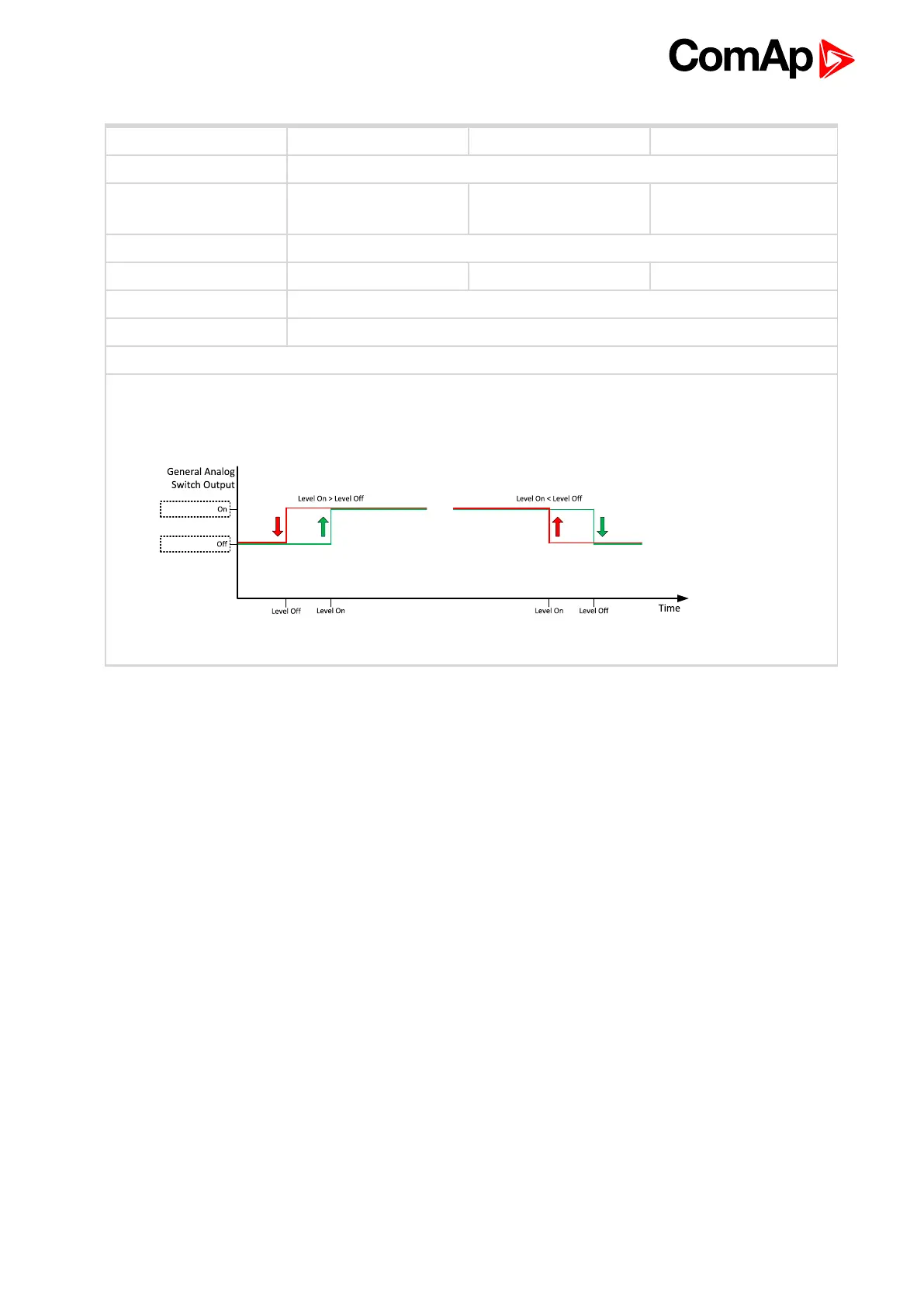
Description
Threshold level for switching the binary output AIN SWITCH 09 (PAGE 662) on. The value is measured from
AIN SWITCH 04 (PAGE 661) analog input.
Image 8.41 General analog input 4 switch
Analog Switch 9 On
6 back to List of setpoints