Home
Comtech EF Data
Transceiver
CSAT-5060
Page 170
Comtech EF Data CSAT-5060 - Page 170
226 pages
Manual
Save Page as PDF
To Next Page
To Next Page
To Previous Page
To Previous Page
Loading...
C-Band Transceiver
Revision 1
CSAT-5060 5 to 25 Watt Installation
MN/CSAT5060.IOM
A–16
Item
Part No.
Nomenclature
QTY
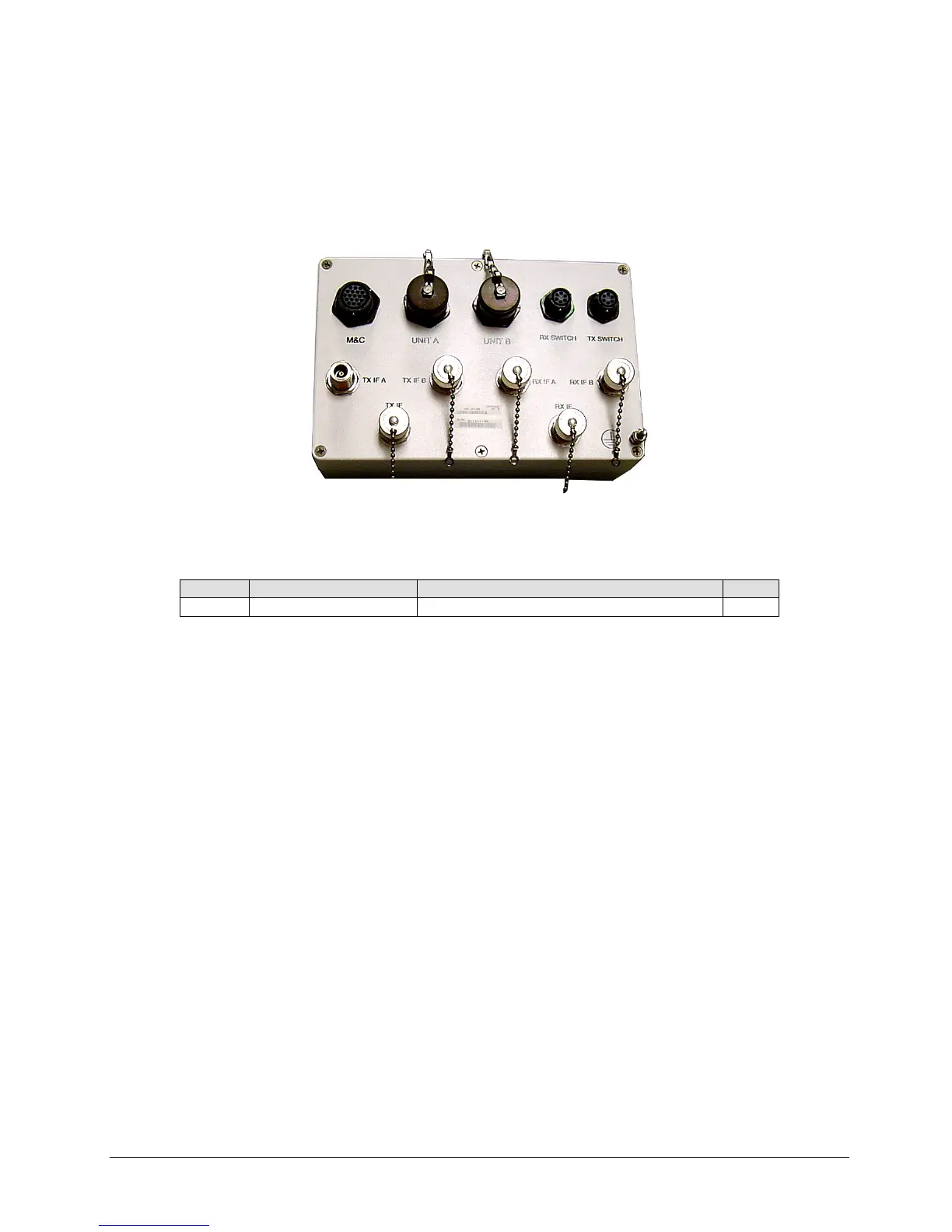
AS/0490
Assembly, Remote Switch Box
1
Figure A-17. Remote Switch Box Assembly, AS/0490
169
171
Table of Contents
Main Page
Blank Page
5
Default Chapter
5
Table of Contents
5
Addendum A. Ethernet-Based Remote Product Management
7
AA.2 Ethernet Management Interface Protocols
8
AA.3 SNMP Interface
8
Lcs?
8
AA.4 Telnet Interface
10
Lna?
10
Lrs=
11
Mac?
21
Onl?
29
Chapter 3. Updating Firmware
35
Updating Firmware Via Internet
35
Ram=
35
Ras?
36
Rcs?
36
Ref?
36
Ethernet-Based Firmware Update Procedure
37
Ret?
37
Rls?
38
Rms?
39
Rrs?
39
Rtg=
52
Rus?
53
Sbr=
57
Sfs?
59
Sna=
61
Snm=
62
Spa=
62
Table of Contents
70
Default Chapter
75
Table of Contents MN/CSAT5060.IOM
75
Customer Support
77
Preface
77
About this Manual
78
Cautions and Warnings
78
Conventions and References
78
Reporting Comments or Suggestions Concerning this Manual
78
Trademarks
78
En 60950
79
Low Voltage Directive (LVD)
79
Safety Compliance
79
Safety Notice
79
Installation Guidelines Regarding Power Line Quality
80
Limitations of Warranty
81
Warranty Policy
81
Exclusive Remedies
82
Ssc=
82
Chapter 1. INTRODUCTION
83
Description
83
Theory of Operation
85
RF Signal Conversion
86
Downconverter
86
Figure 1-1. Functional Block Diagram of the Downconverter Section
86
Upconverter
87
Figure 1-2. Functional Block Diagram of the Upconverter Section
87
Monitor & Control
88
Chapter 2. SPECIFICATIONS
89
Dimensional Envelope
89
Figure 2-1. CSAT5060 25-Watt Dimensional Envelope
90
Figure 2-2. CSAT5060 50-Watt Dimensional Envelope
91
Figure 2-3 CSAT5060-100 or 125W Dimensional Envelope
92
Figure 2-4 Remote Switch Dimensional Drawing
93
Specifications
95
Chapter 3. CONNECTOR PINOUTS
97
Pin-Outs
97
Table 3-1. -48VDC Input Option
97
Connector J5: COMM, Remote Communications Port
98
Chapter 4. System Operation
99
Turning on the CSAT
99
Configuring the CSAT
99
Frequency
99
Attenuation
100
Gain Offset
100
Mute Mode
100
Mute
101
Tx Amplifier
101
Channel Slope Adjust Mode
101
Channel Slope Adjust
102
Reference Frequency Adjust
102
External Reference Fault Logic
102
Cold Start Function
103
Auto Fault Recovery
103
LNA Current Source
104
LNA Current Calibration and Current Window
104
LNA Fault Logic
104
Redundancy Controller Auto/Manual
105
Redundancy Controller Toggle
105
Set Physical Address
105
Set Baud Rate
106
Set Date
106
Set Time
106
Chapter 5. REDUNDANT SYSTEMS
107
Redundant System
107
Figure 5-1. Typical CSAT Redundant System
107
RSU-5060 Interfaces
108
Electrical Interface
108
CSAT Unit a Interface, J1
108
Table 5-1. RSU-5060 Interface Connectors
108
Table 5-2. CSAT a Signal Description (Connector J1)
108
Rx Waveguide Switch Interface, J2
109
CSAT Unit B Interface, J3
109
Table 5-3. Rx Waveguide Switch Signal Description (Connector J2)
109
Table 5-4. CSAT B Signal Description (Connector J3)
109
Tx Waveguide Switch Interface, J4
110
M&C Interface, J5
110
Table 5-5. Tx Waveguide Switch Signal Description (Connector J4)
110
Table 5-6. M&C Signal Description (Connector J5)
110
Tx if Interfaces, J6, J7, and J8
111
Rx if Interfaces, J9 – J
111
Mechanical Interface
111
RSU-5060 Operation
112
Figure 5-2 RSU-5060 Functional Block Diagram
112
RS-485 Interface
113
RED AUTO/MANUAL Signal
113
SWITCH CMD Signal
114
REDUNDANCY A/B Signals
114
REDUND_FLT Signal
114
AUXCOM Signals
114
Configuring a Redundant System
115
Chapter 6. REMOTE CONTROL
117
Introduction
117
Table 6-1. RS-485 Interface
117
Table 6-2. RS-232 Interface
117
Basic Protocol
118
Packet Structure
119
Start of Packet
119
Table 6-3. Master-To-Slave
119
Table 6-4. Slave-To-Master
119
Address
120
Instruction Code
120
Instruction Code Qualifier
120
Message Arguments
122
End of Packet
122
Commands or Responses
122
Ssn=
128
Sta=
130
Chapter 7. MAINTENANCE and TROUBLESHOOTING
137
Figure 7-1. Converter Signal and Interconnecting Cable Diagram
137
Maintenance Testing
138
Troubleshooting
138
Converter Faults
138
DC Power Supply Voltages
138
RF Converter Module
139
Reference Oscillator Module
139
LNA Curent Fault
139
Fan Fault
140
Temperature Fault
140
Chapter 8. LNA INSTALLATION
141
LNA Installation
141
Tools Required
141
LNA Mounting Kits
141
Figure 8-1. Mounting LNA Switch Kit, AS/0438
142
Figure 8-2 TX/RX Filter Support Bracket, AS/0502
143
Figure 8-3. Waveguide Kit, CPR229, AS/0461
144
Assemble LNA Switch Kit, AS/0438
145
Installation of LNA Assembly
146
Single-Thread LNA Installation
146
Redundant LNA Installation
147
Chapter 9. CSAT-5060 +10 Dbm Unit
149
9.1 Overview
149
Function Description
150
9.1.2 Prime Power Level
150
9.1.3 Physical Dimensions
150
Specifications
151
Appendix A. CSAT-5060 5 to 25 Watt INSTALLATION
155
Unpacking and Inspection
155
Man-Power
155
Tools Required
155
Single-Thread Configuration
156
Mounting Kit
156
Table A-1. Universal Pole Mount, AS/0599
156
Single-Thread Installation
159
Cable Installation
162
SPAR-Mount Installation
163
Mounting Kit
163
Mounting Instructions
165
Cable Installation
166
Redundancy Configuration
167
Mounting Kit
167
Swc=
171
Assemble Tx/Remote Switch, AS/0503
172
Connect Cabling to the Remote Switch Box, AS/0490
173
Redundancy Installation
174
Cable Installation
176
Appendix B. CSAT-5060 50-Watt INSTALLATION
179
Unpacking and Inspection
179
Personnel
179
Tools Required
179
Tim=
179
Single-Thread Configuration
180
Mounting Kits
180
Table B-1. Universal Pole Mount, 50 Watt, As/0600
180
Tps=
180
Single-Thread Installation
183
Cable Installation
187
Uat?
187
Redundancy Configuration
188
Mounting Kit
188
Table B-2. Final 1:1, C-Band Assembly
188
Table B-3. 1:1 Mounting Assembly, As/0597
188
Redundancy Installation
194
Assemble Waveguide Switch, AS/0462
195
Assemble Redundant Configuration
196
Cable Installation
200
Appendix C. CSAT-5060 100W or 125W INSTALLATION
203
Unpacking and Inspection
203
Man-Power
203
Tools Required
204
Single -Thread Configuration
204
Mounting Kits
204
Table C-1. Universal Pole Mount, 100 or 125 Watt, AS/0600
204
Single-Thread Installation
207
Cable Installation
210
Redundancy Configuration
211
Mounting Kit
211
Redundancy Installation
217
Assemble Waveguide Switch, AS/0478
218
Assemble Redundant Configuration
219