Low Power Outdoor (LPOD) Amplifier/Block Up Converter (BUC)
Revision 15
System Connectors, Installation, and Startup 2–11 MN-LPOD
PS 1/PS 1.5 PS 2
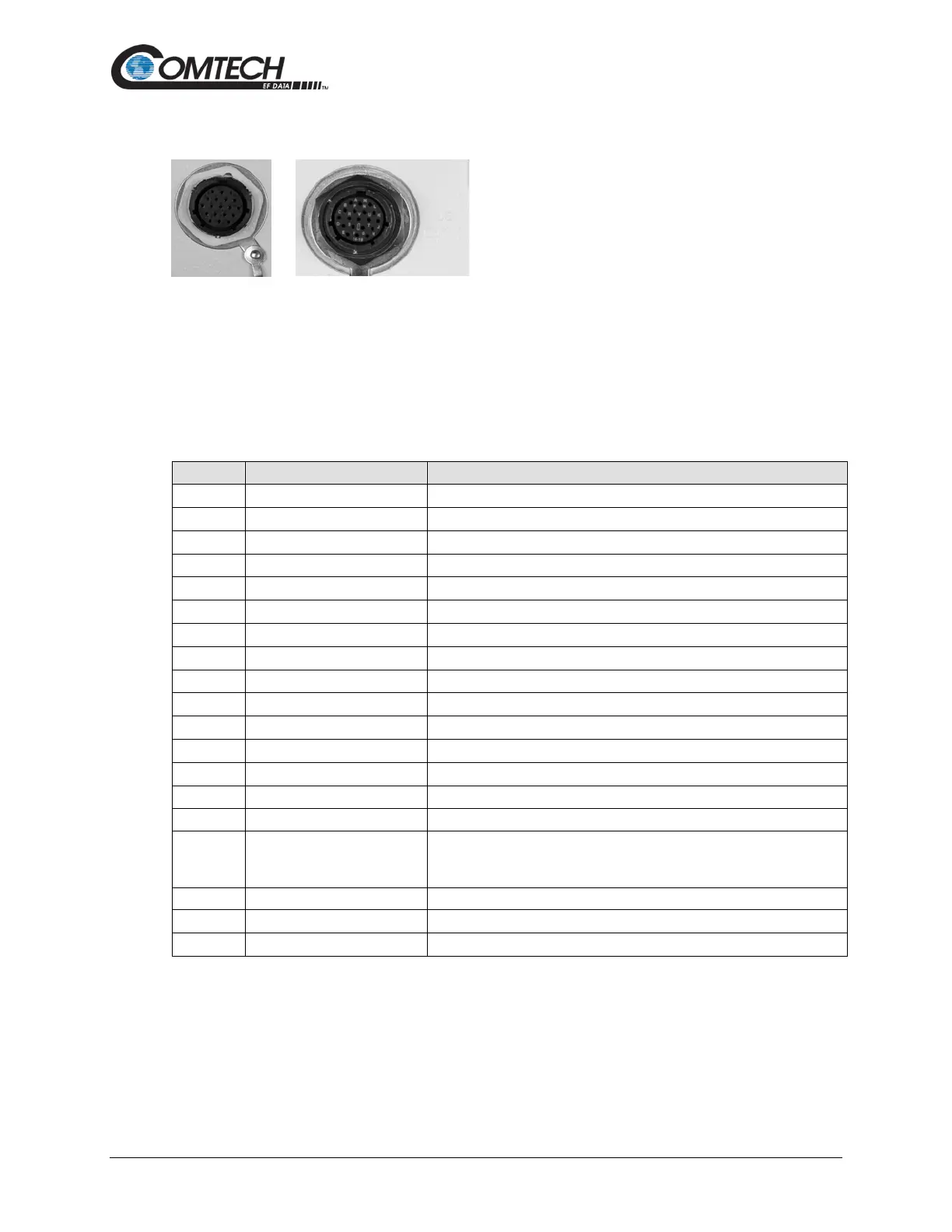
2.3.5 Connector ‘J6 | COM1’ (Remote Communications and Discrete Control
Port)
The ‘J6 | COM 1’ discrete control connector is the primary input for controlling and monitoring the
LPOD. It is a 19-pin circular connector, type MS3112E14-19S.
Mating connector:
MS3116J14-19P or ITT KPT06J14-19P
Table 2-8. ‘J6 | COM1’ Pin Assignments
Pin 3 of DB9 female connector
Pin 3 of RJ45 female connector
Pin 2 of DB9 female connector
Pin 6 of RJ45 female connector
Ground (also Pin 5 of DB-9F connector)
Open when faulted, otherwise+5 VDC
When faulted, tied to Pin K, otherwise open
Online/Offline indication
S System Mute Control
When AUX=1, unit is muted until this pin is tied to ground (Pin K). When
tied to ground, the unit unmutes. See the AUX remote command in
Chapter 5. SERIAL INTERFACE OPERATION.
Pin 2 of RJ45 female connector
Pin 1 of RJ45 female connector