13 | P a g e
THE BASICS - PORT ROUTING
5 Pin Port Routing
The most fundamental use of the MRCC is to route in-ports to out-ports. This is simply done by
choosing any in-port and then routing it by selecting one or more out-ports. When choosing an in-port
the LED will shine green, out-ports shine blue. Notice when making routings using in-port and out-port
buttons the Routing screen page info will follow and match, more on that later.
Example: route in-port 3 to out-port 5. Choose in-port 3 by pressing MIDI IN button #3 (LED
lights green) and select out-port 5 by pressing MIDI OUT button #5 (LED lights bright blue).
Example continued: to route in-port 3 to additional out-ports just press any unlit MIDI OUT
button (LED lights bright blue). To add out-port 7 press MIDI OUT button #7. Now three LEDs
should shine, in-port 3 (green), out-port 5 (dim Blue), and out-port 7 (bright blue). Bright blue
LEDs indicates the selected out-port.
To remove any out-port from the routing it first must be the selected out-port (bright blue LED). If not
already lit brightly, press any dimly lit blue LED out-port button to turn it bright. Press it a second time
and it will go dark and be un-routed from that chosen in-port.
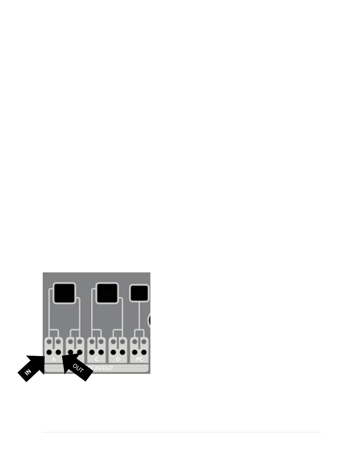
USB Port Routing
Notice that each USB Port has two buttons and two LEDs. This is because USB ports are bi-directional,
meaning they are both an in-port and an out-port. This is different from 5 Pin ports which can only send
or receive information in one direction. For each USB port the button and LED on the left are the in-port
controls and the button and LED on the right are the out-port controls.
USB ports can also support multiple “virtual cables”, which
means that a single physical USB cable can be several virtual
cables. This can be most easily seen from a PC. When you
plug in the MRCC to the PC the PC shows MRCC 1-12 as
available ports.
All the MRCC’s USB HOST ports (A, B, C & D) each support
four inbound “virtual cables” and one outbound. The MRCC’s
USB DEVICE port (aka PC) supports 12 inbound “virtual
cables” and 12 outbound “virtual cables”.
Why the complexity? Some modern sequencers support
“virtual cables” over a single physical USB cable (like the
Conductive Labs NDLR). The MRCC can route each “virtual cable” independently. Another example is
standalone app “soft-synths” on a PC. Often each soft-synth requires its own “virtual cable” as an in-
port. Another example is assigning DAW tracks to separate “virtual cables”.