49 | P a g e
Appendix
A. Optional MIDI Remote Devices (THIS IS NOT ETHERNET!)
The MRCC can be extended via the RJ45 jack on the side of the device labeled “=Y”. It connects to
devices using a straight thru (not cross-over) Cat5 (or higher) shielded cable with shielded connectors.
We have tested up to ~50’ (15m) long cables. The RJ45 connectors must have a metal shield which is
connected to a shield (drain) wire in the cable. This is known as Shielded Twisted Pair (STP). Higher
quality Cat6a cables are typically made with STP wire that includes a drain wire, and are available with
shielded connectors.
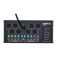
MRCC Remote 7 (R7)
In order to use the R7 it must be first enabled in the Setting Menu#2 – “Enable Remote7: Y”. The R7
works in two modes (as of firmware 1.1.020) either “Copy 1-5” mode or “Remote 1-5” mode, these are
also found in the Setting Menu#2. When a connection is made the “=Y” icon in the upper right corner of
the screen will illuminate.
So where did we get “7” from? Out-port 1 has both 5-Pin DIN and 1/8” TRS type A jacks on the R7, and
out-port 2 has both 5-Pin DIN and 1/8” TRS type B on the R7. In most cases the 5-pin DIN and 1/8” jacks
can be used at the same time, though they are not electrically separated.
“Copy 1-5” mode copies MIDI messages to the R7 out-ports jacks 1-5. So whichever MIDI messages are
routed to MRCC jacks 1-5 also show up on the R7 1-5, they are usable at the same time. The “Y” button
is NOT required to route to these copied ports.
“Remote 1-5” mode extends the number of out-ports by 5. In order to route MIDI messages to an
extended out-port press and hold the “Y” button, then select the desired out-port (1-5). This mode
works the same way routing MRCC out-ports but with Yellow LEDs (not blue). Press and hold the “Y”
button while on the Activity screen and it will say “REMOTE” and show all the remote routings in yellow.
Press and hold the “Y” button while on the Routing screen and it you will see that the out-port names
are prefixed with an “r” i.e. “1 -> r4”
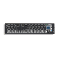
MRCC-to-MRCC “remote” connection
Two MRCCs can connect to each other via the RJ45 cable. When 2 MRCCs are connected they will auto
detect each other and the “=Y” icon in the upper right corner of the screen will illuminate.
The MRCC-to-MRCC connection extends the number of out-ports by 12x 5-pin + 4x USB Host + 1 USB
device ports on the connected MRCC. In order to route MIDI messages to an extended out-port press
and hold the “Y” button, then select the desired out-port. This mode works the same way routing MRCC
out-ports but with Yellow LEDs (not blue). Press and hold the “Y” button while on the Activity screen
and it will say “REMOTE” and show all the remote routings in yellow. Press and hold the “Y” button while
on the Routing screen and it you will see that the out-port names are prefixed with an “r” i.e. “1 -> r4”