Menu 3
Parameter
structure
Keypad and
display
Parameter x.00
Parameter description
format
Advanced parameter
descriptions
Serial comms
protocol
Performance
52 Mentor MP Advanced User Guide
www.controltechniques.com Issue Number: 4
The terminations may be enabled/disabled by this parameter as follows:
Trips can be enabled/disabled using Pr 3.40 as follows:
Encoder trips
The following table shows trips that can be initiated that are related to the drive encoder feedback and whether they can be enabled and disabled by
Pr 3.40.
+These trips can be enabled/disabled by Pr 3.40
1. If the terminations are not enabled on the A, B or Z inputs the wire break system will not operate (5 V or 8 V only). (Note that as default the Z
input terminations are disabled to disable wire break detection on this input.)
Wire-break detection
It may be important to detect a break in the connections between the drive and the position feedback device. This feature is provided for most
encoder types either directly or indirectly as listed below.
Power supply short circuit or overload on drive encoder terminals
There is an overload or short circuit on the drive encoder terminals.
Power supply short circuit or overload on option encoder supply
There is an overload or short circuit on the option encoder power supply.
Both the above trips can over ride trip Enc2 so if there is a wire break trip and then a power supply trip the drive will store both trips in the trip log. Both
the above trips turn the terminal encoder supply off.
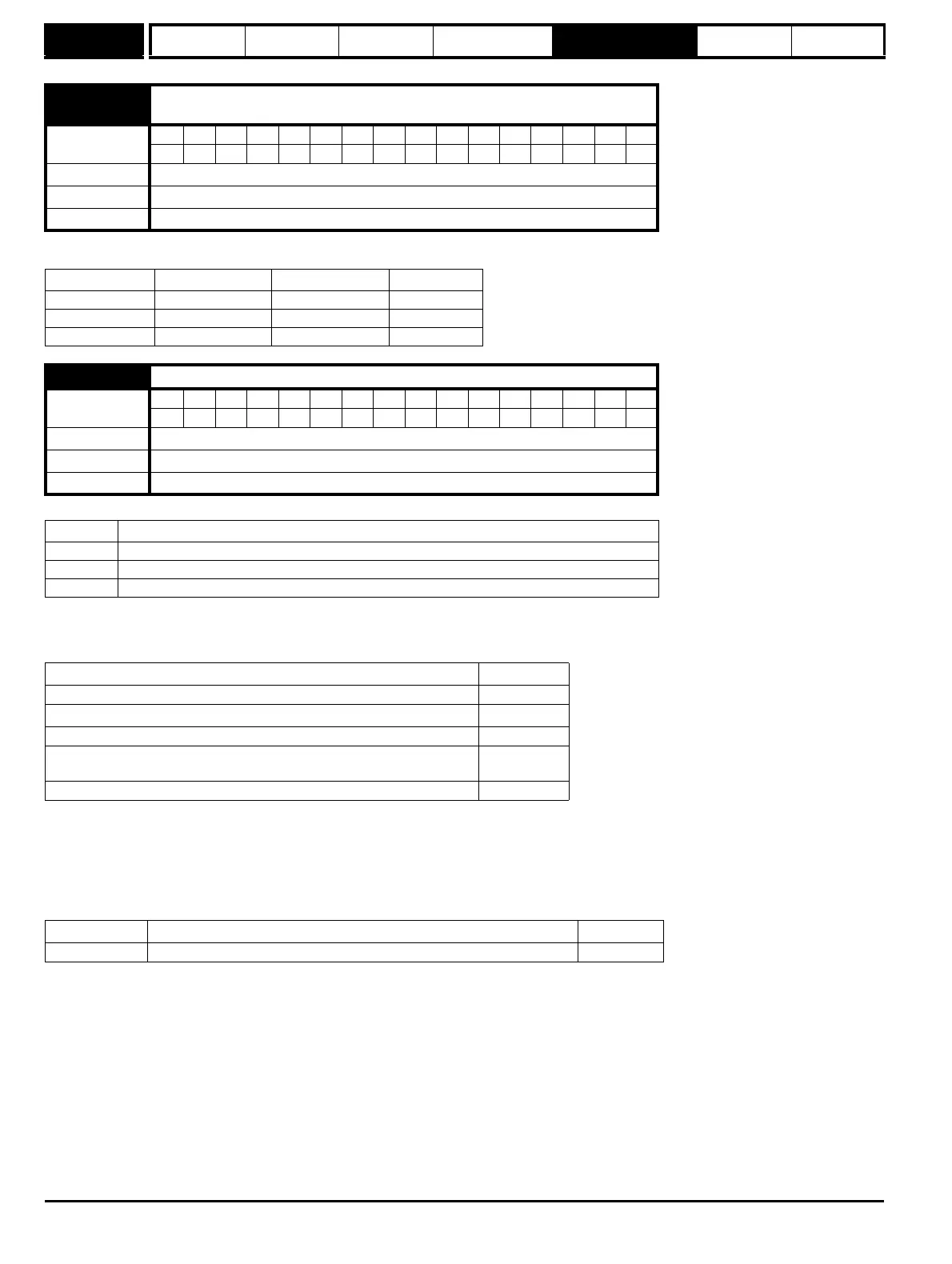
3.39
{Fb08, 0.78}
Drive encoder termination select
Coding
Bit SP FI DE Txt VM DP ND RA NC NV PT US RW BU PS
11
Range 0 to 2
Default 1
Update rate Background read
Encoder input Pr 3.39=0 Pr 3.39=1 Pr 3.39=2
A-A\ Disabled Enabled Enabled
B-B\ Disabled Enabled Enabled
Z-Z\ Disabled Disabled Enabled
3.40
Drive encoder error detection level
Coding
Bit SP FI DE Txt VM DP ND RA NC NV PT US RW BU PS
111
Range 0 to 2
Default 0
Update rate Background read
Bit Function
0 Wire break detect disabled
1 Wire break detect on A and B (need termination enabled for 5 V and 8 V)
2 Wire break detect on A, B and Z (need termination enabled for 5 V signals)
Reason for error Drive trip
Power supply short circuit or overload on drive encoder terminals Enc1
+Hardware wire-break detect on A, B and Z inputs
(1)
Enc2
Power supply short circuit or overload on option encoder supply Enc3
Speed feedback selected from an option slot that does not have a position
feedback category Solutions Module installed
Enc9
Termination Overload Enc10
Device Detection method Drive Trip
Ab, Fd, Fr Hardware detectors on the A(F), B(D,R) and Z signal detect a wire break Enc2