Parameter
structure
Keypad and
display
Parameter x.00
Parameter description
format
Advanced parameter
descriptions
Serial comms
protocol
Performance
Menu 4
Mentor MP Advanced User Guide 65
Issue Number: 4 www.controltechniques.com
This assumes that the maximum allowed motor temperature is produced by 1.05 x Motor rated current and that τ is the thermal filter of the point in the
motor that reaches its maximum allowed temperature first. τ is defined by Pr 4.15. The estimated motor temperature is given by Pr 4.19 as a
percentage of maximum temperature. If Pr 4.15 has a value between 0.0 and 1.0 the thermal filter is taken as 1.0.
When the estimated temperature reaches 100 % the drive takes some action depending on the setting of Pr 4.16. If Pr 4.16 is 0, the drive trips when
the threshold is reached. If Pr 4.16 is 1, the current limit is reduced to 100 % when the temperature is 100 %. The current limit is set back to the user
defined level when the temperature falls below 95 %.
The time for some action to be taken by the drive from cold with constant motor current is given by:
T
trip
= -(Pr 4.15) x ln(1 - (1.05 x Pr 5.07 {SE07, 0.28} / Pr 4.01 {di08, 0.43})
2
)
Alternatively the thermal filter can be calculated from the trip time with a given current from:
Pr 4.15 = -T
trip
/ ln(1 - (1.05 / Overload)
2
)
For example, if the drive should trip after supplying 150 % overload for 60 seconds then
Pr 4.15 = -60 / ln(1 - (1.05 / 1.50)
2
) = 89
Each time the rated current defined by Pr 5.07 {SE07, 0.28} or Pr 21.07 (depending on the motor selected) is altered, the accumulator is reset to zero.
With Pr 4.16 set to 1 or 3 when in slave mode Pr 5.43 = 8 (P.Slave) has no effect on the drive thermal protection.
The current limit applied at any time depends on whether the drive is motoring or regenerating and also on the level of the symmetrical current limit.
Pr 4.18 gives the limit level that applies at any instant.
See Pr 4.16 on page 64.
This parameter displays the current magnitude (Pr 4.01 {di08, 0.43}) as a percentage of rated active current. Positive values indicate motoring and
negative values indicate regenerating.
If this parameter is set to one, the drive calculates a torque reference from the motor and load inertia (Pr 3.18) and the rate of change of speed
reference. The torque reference is added to the speed controller output to provide inertia compensation. This can be used in speed or torque control
applications to produce the torque required to accelerate or decelerate the load inertia.
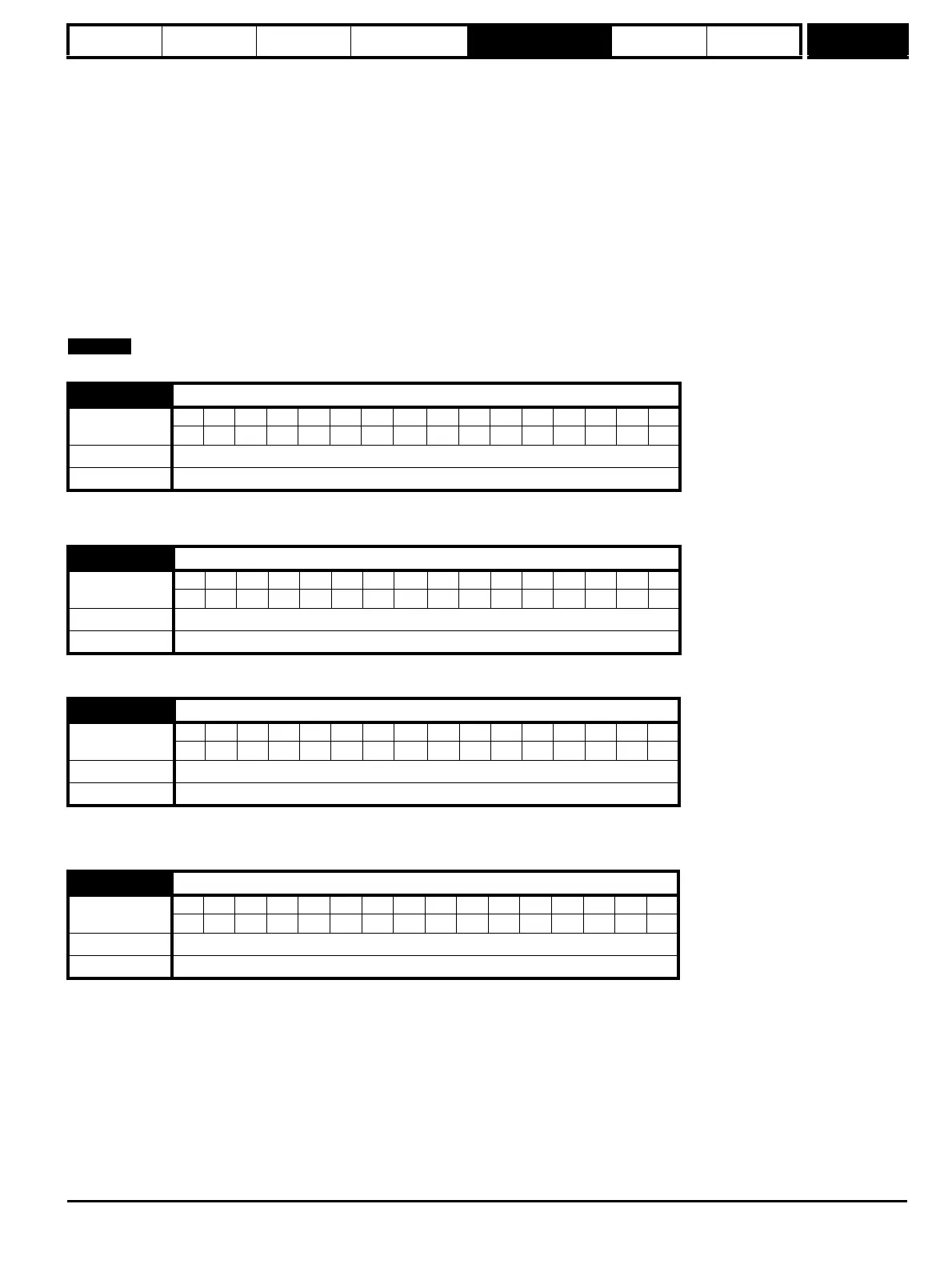
4.18 Overriding current limit
Coding
Bit SP FI DE Txt VM DP ND RA NC NV PT US RW BU PS
111 1 1 1
Range 0 to TORQUE_PROD_CURRENT_MAX %
Update rate Background write
4.19 Overload accumulator
Coding
Bit SP FI DE Txt VM DP ND RA NC NV PT US RW BU PS
11 1 1 11
Range 0 to 100.0 %
Update rate Background write
4.20 Percentage load
Coding
Bit SP FI DE Txt VM DP ND RA NC NV PT US RW BU PS
111111
Range ±USER_CURRENT_MAX %
Update rate Background write
4.22 Inertia compensation enable
Coding
Bit SP FI DE Txt VM DP ND RA NC NV PT US RW BU PS
111
Default 0
Update rate Background read