Menu 4
Parameter
structure
Keypad and
display
Parameter x.00
Parameter description
format
Advanced parameter
descriptions
Serial comms
protocol
Performance
64 Mentor MP Advanced User Guide
www.controltechniques.com Issue Number: 4
The proportional gain Kp (Pr 4.13) is the most critical value in controlling the performance of the current controllers. The value can be set by auto-
tuning (see Pr 5.12 {SE13, 0.34}).
Pr 4.14 = 1697 x L x f x Imax / V rms
Where :
L is the load inductance in Henries
R is the load resistance in ohms
f is the supply frequency in Hertz
Imax is the peak load current (including any overload) in amps
V rms is the line-to-line supply voltage in volts.
The gain values that are calculated by the autotune system give the best response with minimal overshoot. If required the gains can be adjusted to
improve performance as follows:
1. The integral gain (Ki) can be used to improve the performance of the current controllers by reducing the effects of non-linearity. These effects will
be more significant for drives with higher current ratings and higher voltage ratings. If Ki is increased by a factor of 4 it is possible to get up to
10 % overshoot in response to a step change of current reference. For high performance applications, it is recommended that Ki is increased by
a factor of 4 from the autotuned values.
2. It is possible to increase the proportional gain (Kp) to reduce the response time of the current controllers. If Kp is increased by a factor of 1.5 then
the response to a step change of reference will give 12.5 % overshoot. It is recommended that Ki is increased in preference to Kp.
Pr 4.16 = 0 - Drive trips when estimated motor temperature reaches 100 %.
Pr 4.16 = 1 - Drive current limit is limited to 100 % when estimated motor temperature reaches 100 %.
Pr 4.16 = 2 - Drive trips when estimated motor temperature reaches 100 % and accumulator is reset at power-up.
Pr 4.16 = 3 - Drive current limit is limited to 100 % when estimated motor temperature reaches 100 % and accumulator is reset at power-up.
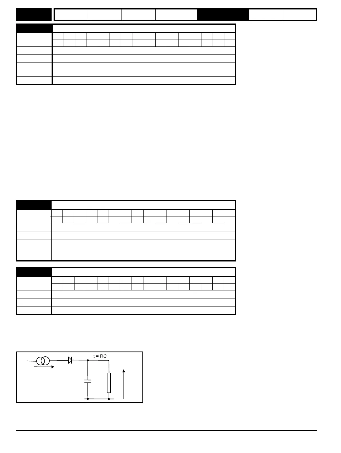
The motor is modelled thermally in a way that is equivalent to the electrical circuit shown as follows.
The temperature of the motor as a percentage of maximum temperature, with a constant current magnitude of I, and constant value of motor rated
current (set by Pr 5.07 {SE07, 0.28} or Pr 21.07) after time t is given by
Temp = [I
2
/ (1.05 x Motor rated current)
2
] (1 - e
-t/τ
) x 100 %
4.14 Continuous current controller Ki gain
Coding
Bit SP FI DE Txt VM DP ND RA NC NV PT US RW BU PS
1 111
Range 0 to 4000
Default 50
Second motor
parameter
Pr 21.14
Update rate Background read
4.15 Thermal filter
Coding
Bit SP FI DE Txt VM DP ND RA NC NV PT US RW BU PS
111
Range 0.0 to 3000.0
Default 89.0
Second motor
parameter
Pr 21.16
Update rate Background read
4.16 Thermal protection mode
Coding
Bit SP FI DE Txt VM DP ND RA NC NV PT US RW BU PS
1111
Range 0 to 3
Default 0
Update rate Background read
I /(1.05*Motor Rated Current)
22
Tem p
C
R