Parameter
structure
Keypad and
display
Parameter x.00
Parameter
description format
Advanced parameter
descriptions
Serial comms
protocol
Performance
Menu 5
Mentor MP Advanced User Guide 93
Issue Number: 4 www.controltechniques.com
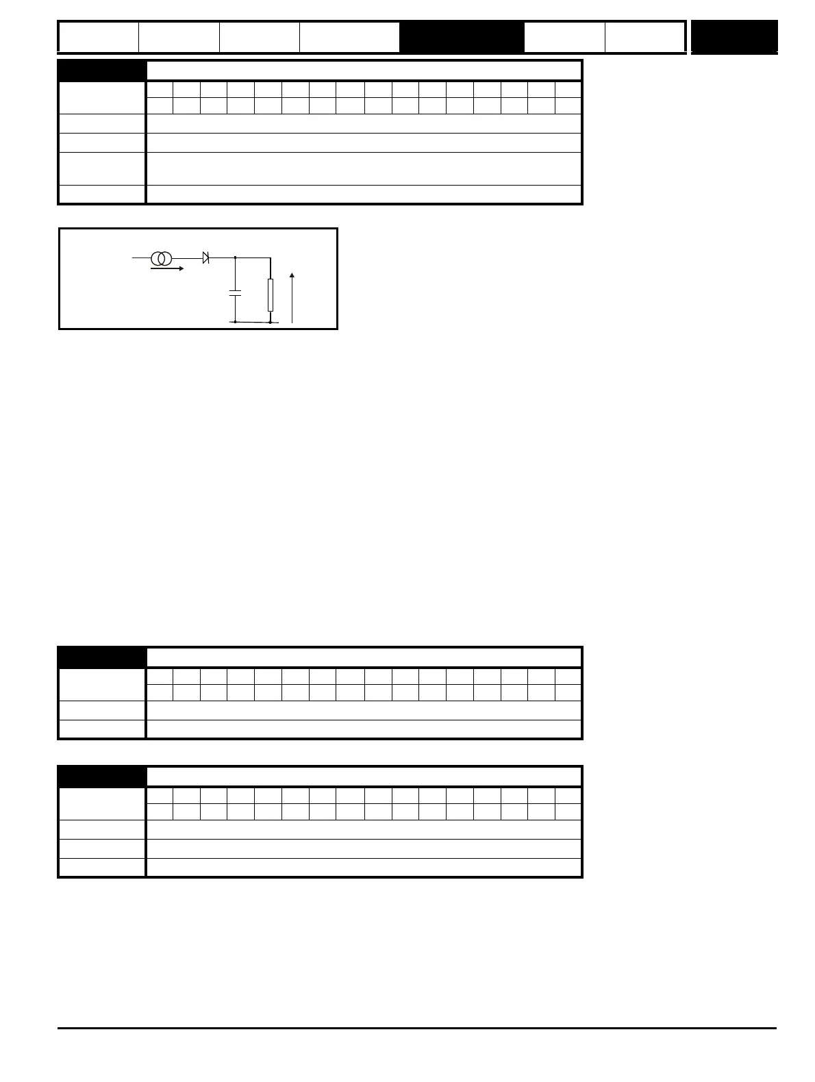
The motor is modelled thermally in a way that is equivalent to the electrical circuit shown below.
The temperature of the field as a percentage of maximum temperature, with a constant current magnitude of I and constant value of field rated current
(set by Pr 5.70 {SE10, 0.31} or Pr 21.24) after time t is given by
Temp = [I
2
/ (1.20*Field rated current)
2
] (1 - e
-t/τ
) x 100 %
This assumes that the maximum allowed field temperature is produced by 1.20 x field rated current and that τ is the thermal filter of the point in the
motor that reaches it maximum allowed temperature first. τ is defined by Pr 5.81. The estimated motor temperature is given by Pr 5.82 as a percent-
age of maximum temperature. If the Pr 5.81 has a value between 0.0 and 1.0 the thermal filter is taken as 1.0.
When the estimated temperature reaches 100 % the drive stops the motor and then trips on F.OVL.
The time for some action to be taken by the drive from cold with constant field current is given by:
T
trip
= -(Pr 5.81) x ln(1 - (1.20 x Pr 5.70 {SE10, 0.31} / Pr 5.56 {di09, 0.44})
2
)
Alternatively the thermal filter can be calculated from the trip time with a given current from
Pr 5.81 = -T
trip
/ ln(1 - (1.20 / Overload)
2
)
For example, if the drive should trip after supplying 125 % overload for 60 seconds then
Pr 5.81 = -60 / ln(1 - (1.20 / 1.25)
2
) = 24
The thermal model temperature accumulator is reset to zero at power-up and accumulates the temperature of the field while the drive remains pow-
ered-up. Each time Pr 11.45 is changed to select a new motor, or the rated current defined by Pr 5.70 {SE10, 0.31} or Pr 21.24 (depending on the
motor selected) is altered, the accumulator is reset to zero.
See Pr 5.81.
With a 2Q drive, the motor can be driven in both the forward and reverse directions by changing the polarity of voltage applied to the field. This mode
of operation can be achieved using a 2Q drive and an external field controller. The flux in the field cannot be reduced until the motor has stopped. The
time taken for the motor direction to change, will depend on how quickly the field flux can be reversed. Figure 5-18 and Figure illustrate the sequence
of events during a forward to reverse and reverse to forward change of direction.
5.81
Field thermal filter
Coding
BitSP FI DETEVMDPNDRANCNVPTUSRWBUPS
1 111
Range
0.0 to 3000.0
Default
24.0
Second motor
parameter
Pr 21.30
Update rate
Background read
5.82
Field overload accumulator
Coding
BitSP FI DETEVMDPNDRANCNVPTUSRWBUPS
11 1 1 1
Range
0 to 100.0 %
Update rate Background write
5.83
Field reversal enable
Coding
BitSP FI DETEVMDPNDRANCNVPTUSRWBUPS
1 1 111
Range
0 to ONLY_2_QUADRANT
Default
0
Update rate
Background read
I
2
/(1.20 x Field Rated Current)
2
τ
= RC
R Temp
C