Do you have a question about the Controls WIZARD 2 50-C92AXX and is the answer not in the manual?
Explains icons used in the manual for notes and warnings.
Lists revisions and dates of the manual.
Defines symbols used on the equipment and in the manual.
Describes the correct and incorrect applications of the machine.
Provides critical safety warnings and responsibilities for users and technicians.
Information on proper disposal of the equipment.
Shows a copy of the CE declaration.
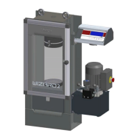
Describes the main structural frame of the machine.
Details the specifications of the compression platens.
Explains the dual-stage hydraulic pump system.
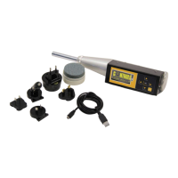
Describes the features of the WIZARD 2 control and display unit.
Illustrates and describes the input/output ports on the equipment.
Location and information on the machine's identification plate.
Details the various buttons and controls on the unit.
Explains the function of the flow control valve.
Lists detailed technical specifications for different models.
Details shipping dimensions, weight, and handling.
Guides on how to unpack and inspect the equipment for transit damage.
Step-by-step instructions for safely removing the machine from its crate.
Guidelines for selecting a suitable installation location and space.
Instructions for attaching the control unit to the frame.
How to adjust the display for optimal visibility.
Specifies voltage, frequency, and power requirements.
Details how to connect power and sensors.
Explains how to connect hydraulic hoses for the frame.
Instructions for installing the printer paper roll.
Steps to power on and initialize the machine.
Overview of the main menu options and navigation.
How to set up and start a test.
Accessing and managing stored test data.
Settings for clock, units, language, etc.
Setting the date and time.
Selecting measurement units (kN, Ton, Lbf).
Erasing stored test data.
Configuring print and save options for test results.
Selecting the display language.
Accessing the calibration menu for adjustments.
Quick guide for performing a test.
How to select between frames on dual-frame models.
Operating the load control valve for different test phases.
Step-by-step process for conducting a sample test.
How to use the emergency stop button.
Procedure for safely powering down the equipment.
Daily, weekly, and monthly checks by the operator.
Verifying the functionality of safety features like emergency stop.
How to check and refill hydraulic oil.
Maintenance tasks for qualified service personnel.
Procedure for ensuring proper ram alignment.
Inspecting for oil leaks in the hydraulic system.
Inspecting distance pieces for damage and wear.
Maintenance of the spherical seat component.
Verifying the accuracy of load measurement channels.
The process of verifying calibration accuracy.
Steps to adjust calibration coefficients for accuracy.
Procedure for changing the hydraulic oil.
Accessing hidden parameters and service procedures.
Configuring active channels and parameters.
Activating or deactivating the second channel.
Setting full scale and preload values for channels.
Setting or viewing the unit's serial number.
Resetting the unit to factory default settings.
| Brand | Controls |
|---|---|
| Model | WIZARD 2 50-C92AXX |
| Category | Laboratory Equipment |
| Language | English |