Operator’s manual A 222 83
Manuale d’uso A 222 21
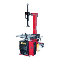
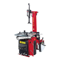
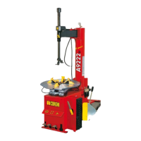
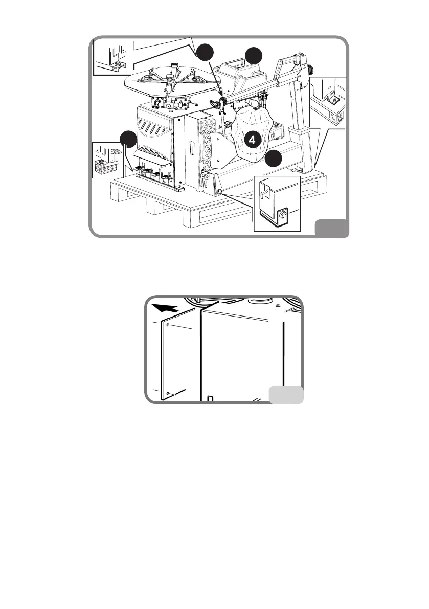
- La macchina è com-
posta da cinque grup-
pi principali (g.4):
1 testata
2 protezione palo
3 scomparto con mano-
metro e dotazione di
serie
4 serbatoio dell'aria
5 cassone
- Dopo aver smontato il palo 1, si consiglia di disporlo in posizione orizzontale per evitare
che possa cadere e danneggiarsi.
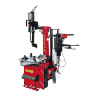
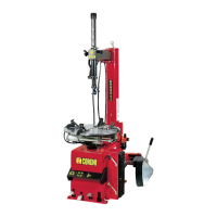
Procedere con il montaggio delle varie parti:
- Togliere il coperchio laterale (Fig. 4a).
- Introdurre il tubo essibile dell'aria G g.5
nel foro A dietro il cilindro ribalta palo.
- Montare il palo 1, inserire il perno B nel
foro C e bloccarlo con vite e rondella D.
4
1
2
5
3
Assemble the different parts of the machine:
- Remove the side cover (Fig. 4a).
4a
- Insert the air hose G fig.5 into hole A behind the tower tilt cylinder.
- Assemble the tower 1, insert pin B into hole C and lock with screw and washer D.
- Insert pin E into hole F and into U-bolt F1 on the tower tilt cylinder and lock with ring M.
- Connect hose G to the intermediate connection linked to the tower-lifting cock H.
- Fit the box with pressure gauge 3 on to the tower 1.
- Fit the tower guard 2 and lock with screws and washers L.
- Insert the tank 4 outlet into hose Q. Fix the tank 4 to the machine with nuts and washers