CVC TECHNOLOGIES, INC. CVC 310 OPERATION MANUAL
7 - 7
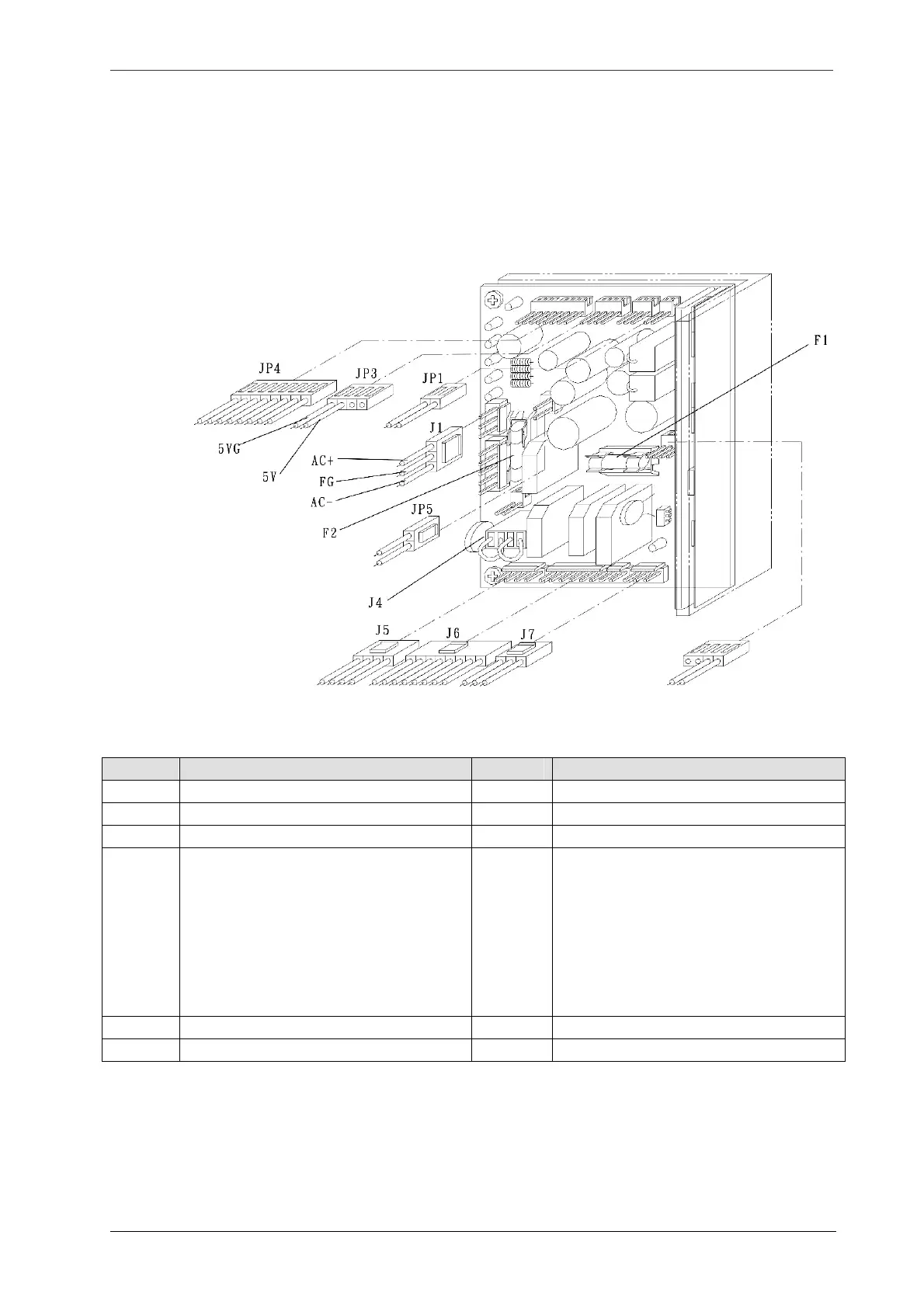
Power Board
a. F2 fuse is burned if transformer is short circuit.
b. Check LED D37 on the interface board. If the three LED is lit, it indicates both the power board and
fuse are not functional. Replace it with a new power board and a new fuse.
Item Function Item Function
J1 AC power JP1 DC 24V
J3 Spare – for future use JP3 DC 5V/12V
J5 Transformer input 110/220V AC -
J6
Transformer output
Blue wire: AC 8V
Green wire: AC 13V
Yellow wire: AC 20V
White wire: AC 110V
JP4 DC 5V/12V
Black wire: 12V
Brown wire: 12VG
Red wire: 12V
Orange wire: 12VG
Yellow and Green wire: 5V
Blue and Purple wire: 5VG
F1 Fuse: 6 Amp (20mm)(Output) F2 Fuse: 6 Amp (20mm) (Input)
J7 DC Voltage output, DC 145V - -