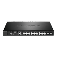
DXS-3326GSR Gigabit Layer 3 Switch
Section 3
Connecting the Switch
Switch To End Node
Switch To Hub or Switch
Connecting To Network Backbone or Server
Stacking and the DXS-3326GSR
NOTE: All 24 high-performance NWay Ethernet ports can support both
MDI-II and MDI-X connections.
Switch To End Node
End nodes include PCs outfitted with a 10, 100 or 1000 Mbps RJ 45 Ethernet Network Interface Card (NIC) and most
routers.
An end node can be connected to the Switch via a twisted-pair UTP/STP cable. The end node should be connected to any
of the four 1000BASE-T ports of the Switch.
Figure 3- 1. Switch connected to an end node
The Link/Act LEDs for each UTP port will light green or amber when the link is valid. A blinking LED indicates packet
activity on that port.
Switch To Hub or Switch
These connections can be accomplished in a number of ways using a normal cable.
A 10BASE-T hub or switch can be connected to the Switch via a twisted-pair Category 3, 4 or 5 UTP/STP
cable.
•
•
•
•
A 100BASE-TX hub or switch can be connected to the Switch via a twisted -pair Category 5 UTP/STP cable.
A 1000BASE-T switch can be connected to the Switch via a twisted pair Category 5e UTP/STP cable.
A switch supporting a fibre optic uplink can be connected to the Switch’s SFP ports via fiber-optic cabling.
14
 Loading...