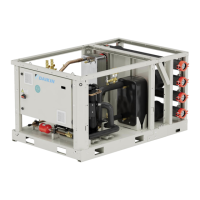
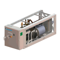
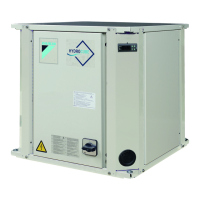
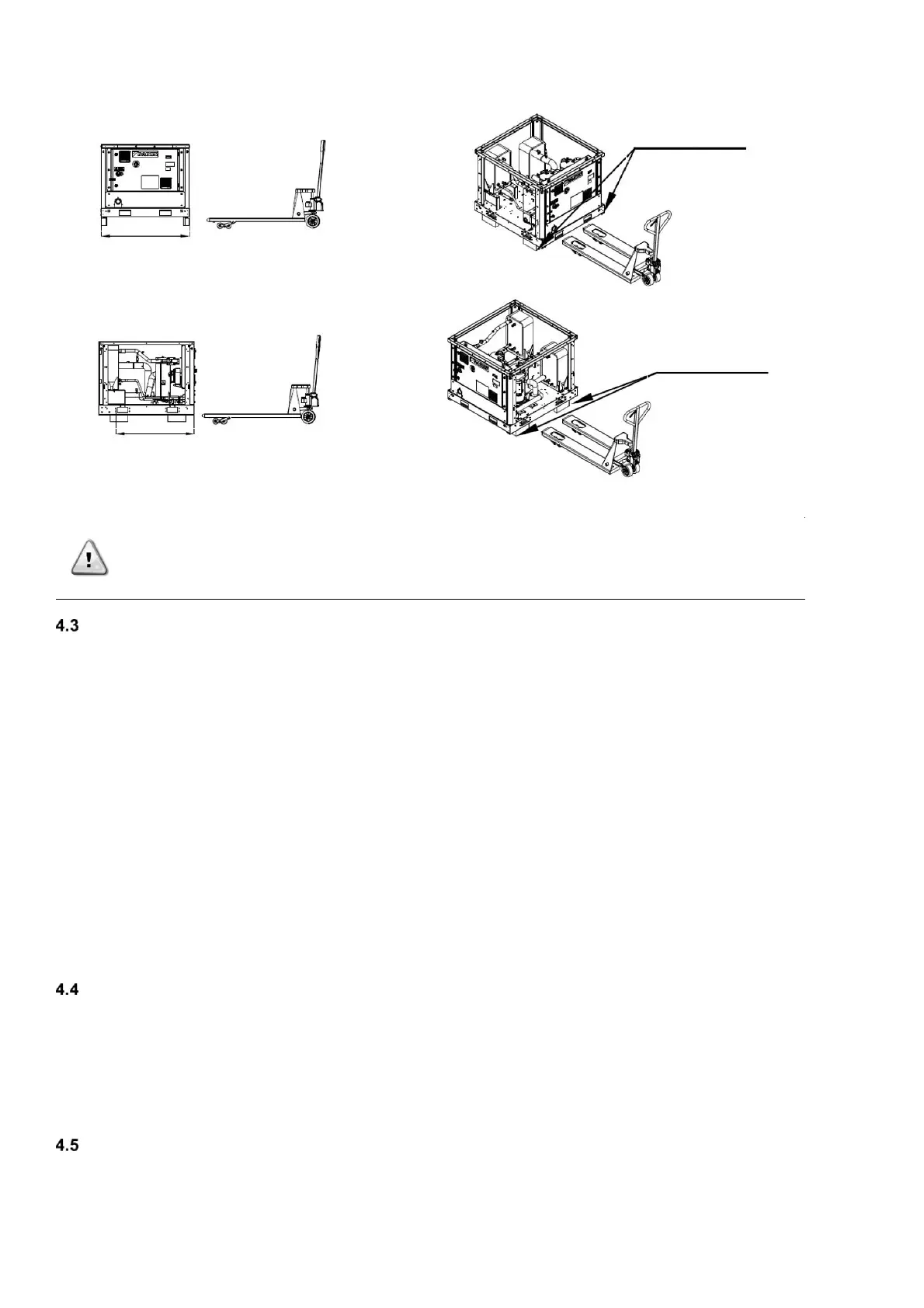
Positioning and assembly
The unit must be installed on a sturdy and perfectly level foundation. For installation on the ground, a resistant concrete base must
be created with a width greater than that of the unit. This base must be able to support its weight.
Anti-vibration supports must be installed between the frame of the unit and the concrete base of the steel beams; for their
installation follow the dimensional drawing provided with the unit.
The frame of the unit must be perfectly levelled during installation, if necessary, using shims to be inserted under the anti-vibration
elements.
Before the first start-up, it is mandatory that the installation be verified as being level and horizontal using a laser level or another
suitable instrument.
The error in the levelness and the horizontal position must not be greater than 5 mm per unit up to 7 metres and 10mm per unit
over 7 metres.
If the unit is installed in places that are easily accessible to people and animals, we recommend that protection grates be assemble
all around to prevent free access. To guarantee the best performance in the place of installation, the following precautions and
instructions must be respected:
- Make sure to provide a strong and solid foundation to reduce noise and vibrations.
- Avoid installing the unit in areas that could be dangerous during maintenance operations, such as platforms without parapets,
railings or areas not complying with the requirements to leave a clearance space all the way around it.
Respect the minimum access distances around the unit 1000 mm all around the unit
For further solutions, please consult manufacturer representative.
Noise and sound protection
The noise generated by the unit is mainly due to the rotation of compressors.
The noise level for each model size is listed in sales documentation.
If the unit is correctly installed, operated and maintained the noise emission level do not require any special protection device to
operate continuously close to the unit without any risk.
In case of installation with special noise requirements it could be necessary to install additional sound attenuation devices.
When sound levels require special control, great care must be exercised to isolate the unit from its base by appropriately applying
anti-vibrating elements, provided as optional. Flexible joints must be installed on the water connections, as well.
Water circuit for the connection of the unit
4.5.1 Water piping
The pipes must be designed with the lowest number of elbows and the lowest number of vertical changes of direction. In this way,
installation costs are reduced considerably, and system performance is improved.
The water system must have:
1. Anti-vibrating pipes which reduce the transmission of vibrations to the structures.