D-EIMHP01702-23_00EN- 53/72
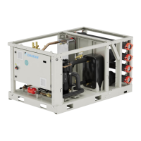
Fig. 51 – Details of cables routing
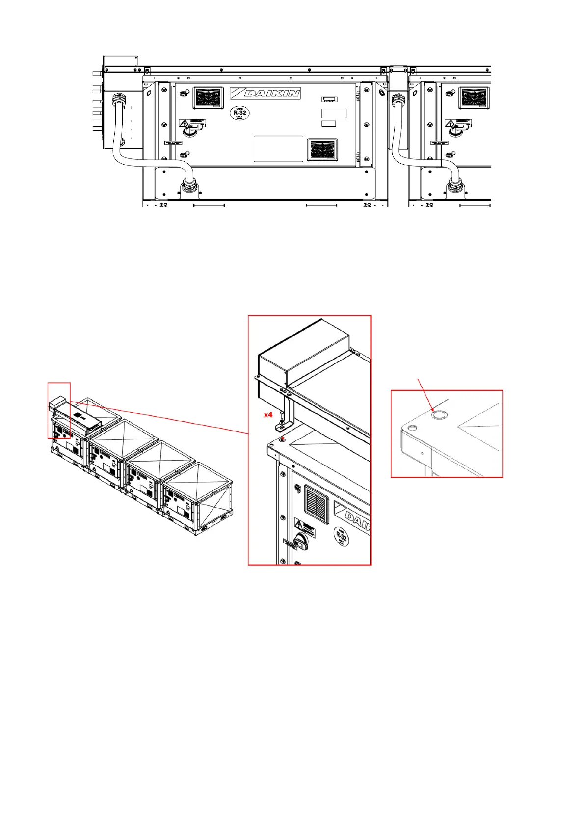
7.8.1 Power bar system mechanical installation
For a correct mechanical installation each power bar module has to be put on top of the proper unit module and fixed with 4 screws
using the hexsert mounted on the lateral crossbeams (2 on each side). When the top panel of the cabinet is present (XR unit version),
a part of the sheet needs to be cut to allow the fastening of the screws.
The first and the last unit module have a proper power bar module with a box that allow the installation of the power cables, the other
units have a specific power bar module without the box.
Fig. 52 – Fixing of the power bar system to the unit
Two consecutive modules have to be connected by a connection module. This module includes 4 busbar connecting terminal in order
to guarantee the electric continuity through the power bar modules.