EasyManua.ls Logo

Daikin EWWT100Q - Reference Drawing in Case of Custom Water Piping; Connection of Modular System; Mechanical Connection; Fig. 25 - Water Piping Configuration

Daikin EWWT100Q
72 pages
Print Icon
To Next Page IconTo Next Page
To Previous Page IconTo Previous Page
Loading...
D-EIMHP01702-23_00EN- 41/72
7.1.3 Reference drawing in case of custom water piping
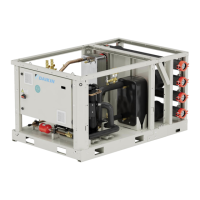
In case the manifold module is not provided by Daikin, it is possible to refer to the following indication for customer piping connection.
Fig. 25 Water piping configuration
When pump module is not equipped, the customer can connect the plant water piping indifferently to the left or right side of the
manifold modules system. When pump module is supplied, the water connection can only be done to the pump suction pipe.
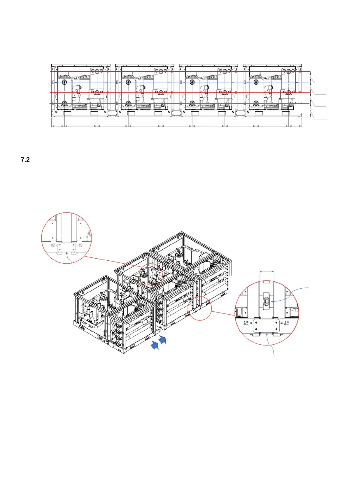
Connection of modular system
7.2.1 Mechanical connection
The mechanical connection of more modular systems together is possible thanks to a positioning kit.
The positioning kit allows to align perfectly the two systems for a proper connection.
Fig. 26 Modular systems connection
Positioning kit for
modular system
Positioning kit for
modular system
Victaulic
connection
3” or 5”
100 mm
(3.94 inches)
[7.8 inches]
197.5 mm
[7.9 inches]
200 mm
[10.3 inches]
260.5 mm
CONDENSER IN
EVAPORATOR OUT
(FOR EWWT)
EVAPORATOR IN
(FOR EWHT)
CONDENSER OUT
EVAPORATOR IN
(FOR EWWT)
EVAPORATOR OUT
(FOR EWHT)
[7.9 inches]
200mm
[10.5 inches]
268 mm
[26.2 inches]
665 mm
[25.0 inches]
635 mm
[26.2 inches]
665 mm
[25.0 inches]
635 mm
[26.2 inches]
665 mm
[25.0 inches]
635 mm
[26.2 inches]
665 mm
[10.5 inches]
268 mm

Table of Contents

Related product manuals