D-EIMHP01702-23_00EN- 31/72
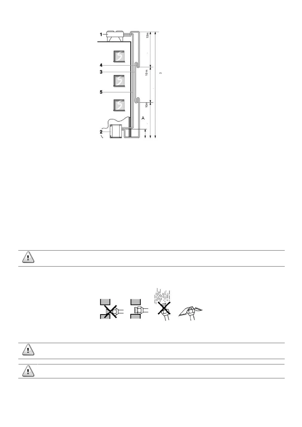
Fig. 17 – Connecting the refrigerant circuit (1)
piping length: equivalent = 50 m maximum height = 30 m
• It is highly recommended, prior to the installation of the units, to perform a vacuum within the piping system using a 2-stage
vacuum pump with a non-return valve that can evacuate to a gauge pressure of −100.7 kPa (−1.007 bar) (5 Torr absolute).
Then, once the vacuum is completed, let the system in vacuum for at least 2 hours. After that, pressurise the system with
nitrogen gas to a maximum gauge pressure of 4.0 MPa (40 bar). Never set the gauge pressure higher than the maximum
operation pressure of the unit, i.e., 4.0 MPa (40 bar).
Once the connecting operations begins, is it possible to depressurize the system letting the nitrogen inside flow out of the piping
system.
• Connect the refrigerant piping securely before running the compressor. If the refrigerant piping is NOT connected when the
compressor is run, air will be sucked in. This will cause abnormal pressure in the refrigeration cycle, which may result in
equipment damage and even injury.
• There should be no blockage (stop valve, solenoid valve) between the remote condenser and the provided liquid injection
of the compressor.
When inserting the refrigerant piping though a wall, take care not to let dust or moisture come into the piping.
Protect the pipes with a cap or seal the pipe end completely with tape.
Use caution when passing copper tubes through walls.
Fig. 18 – Connecting the refrigerant circuit (4)
The discharge and liquid line are to relate to flare connections to the remote condenser piping. For use of the correct pipe diameter
see "Technical specifications".
Be sure that the field installed piping does not touch other pipes, the bottom panel or side panel. Especially for
the bottom and side connection, be sure to protect the piping with suitable insulation, to prevent it from coming
into contact with the casing.