D-EIMHP01702-23_00EN- 40/72
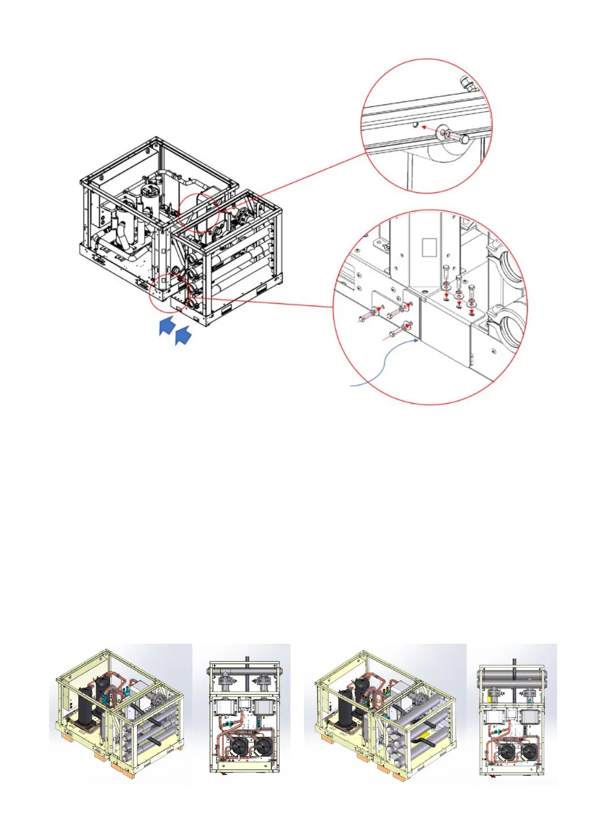
Fig. 23 – Connection instructions between chiller and manifold modules
After installation of manifold module and before connection to the chiller module, it is important to clean and remove welding oxides
and other contamination products deriving during production of the water piping.
The cleaning steps are the following:
1. Flush the pipes with a solution of hot water and a mild detergent.
2. Flush with a dilute solution of phosphoric acid
3. Stop the cleaning when no more debris are visible.
4. After the cleaning, flush the pipes for one hour with cold water to remove any residue.
All the cleaning liquids, acids, and detergents must be compatible with stainless steel, copper, and carbon steel. Consult a
professional water treatment specialist when in doubt.
The manifold module is equipped with a butterfly valve in each pipe.
7.1.2 Partial Heat Recovery with manifold module
In case the unit with optional Partial Heat Recovery (PHR) is installed with the manifold module, to connect the PHR exchanger pipes
the following precautions can be followed: when the system is made up of multiple modules, it is recommended to have the PHR
pipes come out between the manifold pipes, like the black pipes in the following pictures.
Fig. 24 – PHR pipes with manifold module (at left for 3inch – at right for 5inch manifold pipes)