D-EIMHP01702-23_00EN- 28/72
4.5.2.5 Connecting the counter pipes
1. Weld the supplied counter pipes to the ends of the water circuit and connect to the unit with the provided Victaulic®
couplings.
2. Drain taps must be provided at all low points of the system to permit complete drainage of the circuit during maintenance
or in case of shut down. The drain plug is provided to drain the condenser. When doing this, also remove the air plugs
(refer to the outlook diagram).
3. Air vent must be provided at all high points of the system. The vents should be located at points which are easily
accessible for servicing.
4. Shut-off valves should be provided at the unit so that normal servicing can be accomplished without draining the system.
5. Vibration eliminators in all water piping connected to the chiller are recommended to avoid straining the piping and
transmitting vibration and noise.
4.5.3 Piping insulation
The complete water circuit, including all the pipes, must be insulated to avoid condensate from forming and reducing the cooling
capacity.
Protect the water pipes from freezing during the winter (using for example a glycol solution or a heating cable).
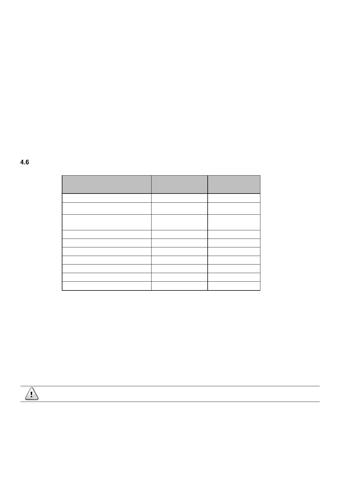
Water treatment
Table 2 - DAE Water quality requirements
The water in the system must be particularly clean and all traces of oil and rust must be removed. Install a mechanical filter at the
entry of every heat exchanger. The failure to install a mechanical filter allows solid particles and/or welding burrs to get inside the
exchanger. We recommend installing a filter with a filtering mesh with holes not larger than 1.1mm in diameter.
The manufacturer cannot be maintained responsible for any damage to the exchangers if the mechanical filters are not installed.
Before putting the unit into operation, clean the water circuit. Dirt, scales, debris, and other material can accumulate inside the heat
exchanger and reduce both its heat exchanging capacity and the flow of the water.
An adequate treatment of the water can reduce the risk of corrosion, erosion, scale formation, etc. The must suitable treatment
must be selected depending on the place of installation, considering the water system and the characteristics of the water.
The manufacturer is not responsible for any damages or malfunctions of the equipment.
The quality of the water must comply with the specifications listed in the following table.