D-EIMHP01702-23_00EN- 30/72
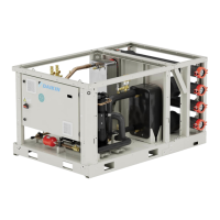
5 GUIDELINES FOR REMOTE CONDENSER APPLICATION (EWLT-Q VERSION)
Design of remote condenser application, and sizing of piping and piping path, is a responsibility of plant designer.
This paragraph is only focused to give suggestion to plant designer, different solutions can be considered with references to
application peculiarities.
For remote condenser application, such as air-cooled or evaporative condensers, the chillers are shipped with holding nitrogen
charge. It is important that the unit be kept tightly closed until the remote condenser is installed and piped to the unit.
Chillers are supplied with filter drier, moisture indicator and expansion valve factory mounted as standard.
It is the contractor responsibility to install the interconnection piping, leak test it and the entire system, evacuate the system and
supply the refrigerant charge.
All piping must be compliant to the applicable local and state codes.
Use refrigerant grade copper tubing only and isolate the refrigeration lines from building structures to prevent transfer of
vibration.
It is important that the discharge lines be looped at the condenser and trapped at the compressor to prevent refrigerant.
and oil from draining into the compressors; looping the discharge line also provide greater flexibility.
Do not use a saw to remove end caps. This might allow copper chips to contaminate the system. Use a tube cutter or
heat to remove caps. When sweating copper joints, it is important to flow dry nitrogen through the system prior to
charging with refrigerant. This prevents scale formation and the possible formation of an explosive mixture of refrigerant.
and air. This will also prevent the formation of toxic phosgene gas, which occurs when the refrigerant is exposed to open.
flame.
Soft solders are not to be used. For copper-to-copper joints use a phosphorous-copper solder with 6% to 8% silver content. A
high silver content brazing rod must be used for copper-to-brass or copper-to-steel joints. Only use oxyacetylene
brazing.
After the equipment is correctly installed, leak tested and evacuated, it can be charged with refrigerant and started under t he
supervision of Daikin authorized technician.
Total refrigerant charge will depend on the used remote condenser and volume of refrigerant piping.
Selection of piping material
1- Foreign materials inside pipes (including oils for fabrication) must be 30 mg/10 m or less.
2- Use the following material specification for refrigerant piping:
- construction material: Phosphoric acid deoxidized seamless copper for refrigerant.
- size: Determine the proper size referring to "Technical specifications”.
- the pipe thickness of the refrigerant piping must comply with relevant local and national regulations.
For R32 the design pressure is 49 bar.
3- In case the required pipe sizes (inch sizes) are not available, it is also allowed to use other diameters (mm sizes), taken
the following into account:
- select the pipe size nearest to the required size.
- use the suitable adapters for the change-over from inch to mm pipes (field supply).
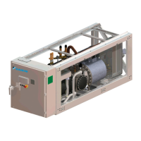
Installation information for condenserless units
This product is factory charged with N2 (holding charge)
The units are equipped with a refrigerant inlet (discharge side) and a refrigerant outlet (liquid side) for the connection to a remote
condenser. This circuit must be provided by a licensed technician and must comply with all relevant national and local regulations.
Connecting the refrigerant circuit
When a condenser-less unit is installed below the condensing unit, the following can occur:
• When the unit stops, oil will return to the discharge side of the compressor.
• When starting the unit, this can cause liquid (oil) hammer.
• The oil circulation will decrease
To solve these phenomena, provide oil traps in the discharge pipe every 10m if the level difference is more than 10m.