D-EIMHP01702-23_00EN- 35/72
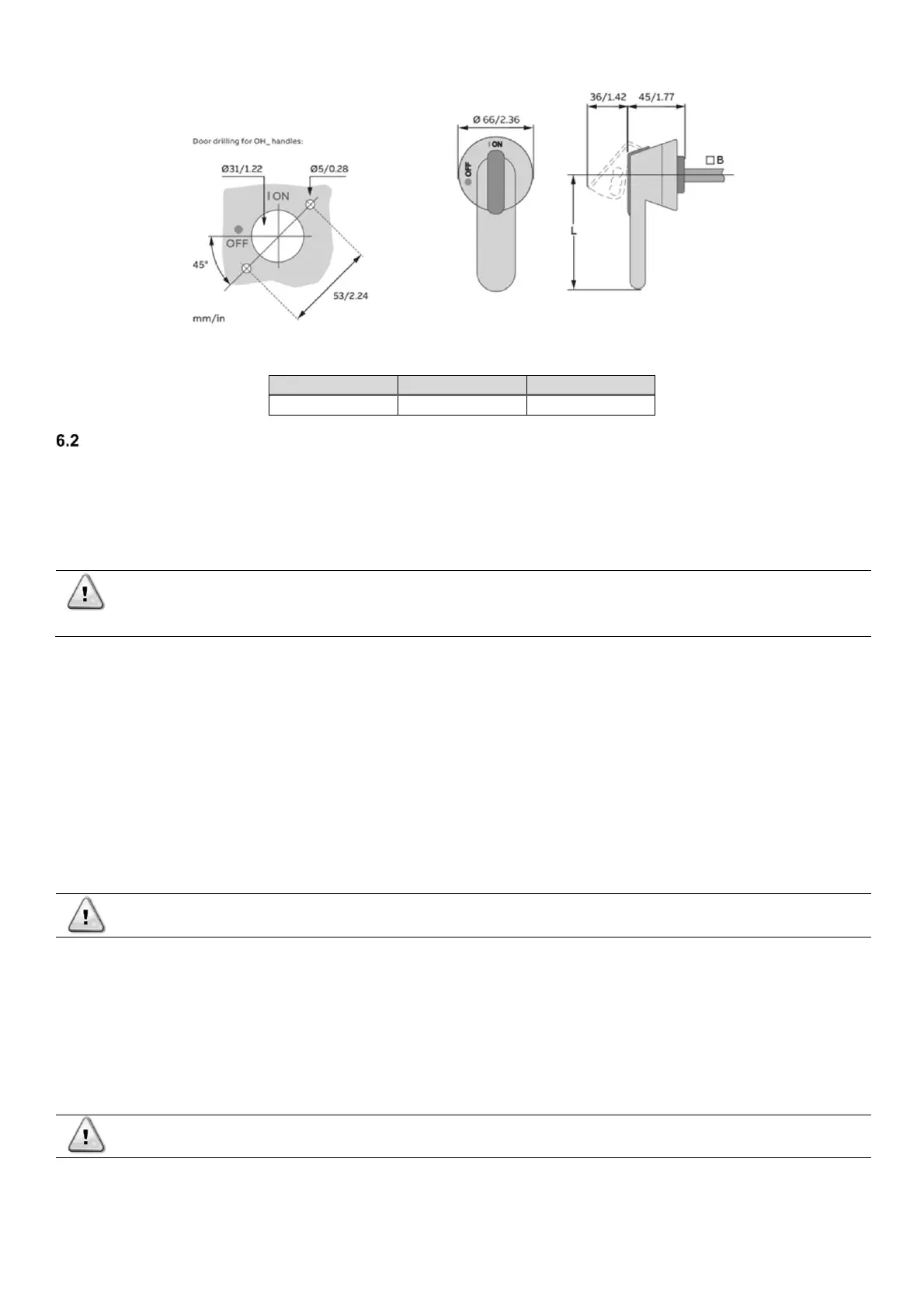
Fig. 21 – Details of the pistol handle
General specifications
Refer to the specific wiring diagram for the unit you have bought. If the wiring diagram is not provided with the unit or if it has been
lost, please contact your manufacturer representative, who will send you a copy.
In case of discrepancy between wiring diagram and electrical panel/cables, please contact the manufacturer representative.
This unit includes non-linear loads such as inverters, which have a natural current leakage to earth. If an Earth Leakage Detector is
installed upstream the unit, a type B device with a minimum threshold of 300 mA must be used.
Before any installation and connection works, the unit must be switched off and secured. Since this unit includes
inverters, the intermediate circuit of the capacitors remains charged with high voltage for a short period of time
after being switched off.
Do not operate to the unit before 20 minutes after the unit has been switched off.
Electrical equipment can operate correctly in the intended ambient air temperature. For very hot environments and for cold
environments, additional measures are recommended (contact the manufacturer representative).
The electrical equipment can operate correctly when the relative humidity does not exceed 50 % at a maximum temperature of +40
°C. Higher relative humidities are permitted at lower temperatures (for example 90% at 20 °C).
Harmful effects of occasional condensation shall be avoided by design of the equipment or, where necessary, by additional measures
(contact the manufacturer representative).
This product complies with EMC standards for industrial environments. Therefore, it is not intended for use in residential areas, e.g.
installations where the product is connected to a low voltage public distribution system. Should this product need to be connected to
a low voltage public distribution system, specific additional measures will have to be taken to avoid interference with other sensitive
equipment.
The units must be connected to a TN power supply system.
If the units must be connected to a different type of power system, for example the IT system, please contact the factory.
All the electrical connections to the unit must be carried out in compliance with national laws and European
directive and regulations in force.
All installation, management and maintenance activities must be carried out by qualified personnel.
Refer to the specific wiring diagram for the unit purchased. Should the wiring diagram not be on the unit, or should it have been
lost, please contact the manufacturer representative who will send you a copy.
In case of discrepancy between the wiring diagram and the visual check of the electric wires of the command-and-control panel,
contact the manufacturer representative.
Use only copper conductors to avoid overheating or corrosion in the connection points, with resulting risk of damage to the unit.
To avoid interference, all the command-and-control cables must be connected separately from the power ones, using several
raceways for this purpose.
Before performing service operations on the unit, open the general disconnection switch located on the main power supply.
If the unit is off but the disconnection switch is in the closed position, the circuits not being used will still be
active.
Never open the terminal board of the compressors without having disconnected the main switch of the machine.
Simultaneous mono and three-phase loads and imbalance between the phases can cause leakage towards earth up to 150mA
during the normal operation of the unit.
The protections for the power supply system must be designed based on the values mentioned above.