Points to Bear in Mind at the System Design SiE33-102
10 General Information
2.4.2 Main Considerations in Preparation of Control Circuit Diagrams
In addition to the design of the appropriate this system configuration it is also essential that the control
stsyem be made amply clear. If the system is designed and installed without a clear, comprehensive plan
then problems are inevitably going to occur during the test run.
Servicing too will become much more time consuming than necessary. However, if control circuit diagrams
are prepared along with the contract drawings in order to make the total system clearly visible then the
essential points relating to the electrical connections will be easily understood, the test run will go off
without a hitch and the whole system will be rendered fully effective.
Step 1: Compiling a
System List
(example using
Inverter K Series)
1. Mark each outdoor unit with a code.
2. Add field settings and data for outdoor units, and outdoor unit No. if using sequential start.
3. Add the model number of each indoor unit connected to each refrigerant circuit.
4. Assign each indoor unit a code.
5. Fill in the location of each indoor unit.
6. Group indoor units controlled by one or two remote controls. (group or individual control).
7. Assign central group Nos. if using centralized control.
8. Add field settings and optional equipment for indoor units.
9. Add unit No. if making separate field settings for each indoor unit under group control.
Note: With the R-22 PLUS Series, unit No. is determined through automatic addressing, therefore readout unit
Nos. after activating the power.
For details on field settings and centralized control group No., refer to the installation manual and system
reference materials.
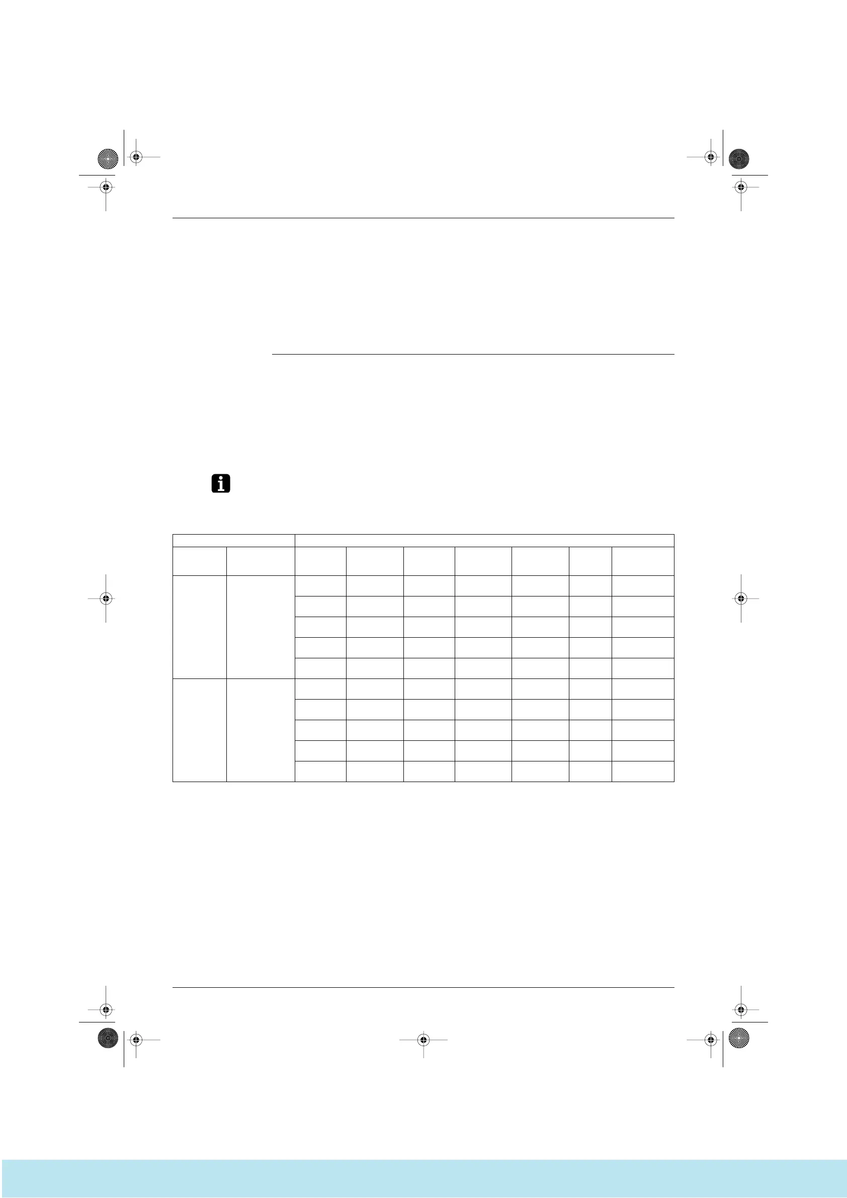
Example: System list
Outdoor Unit Indoor Unit
Model Name
(code)
Field Settings Model Name System Name Location
Remote
Control Group
Centralized
Control Group
No.
Unit No.
Optional
equipment, field
settings, etc.
RSXY16KA
(PAC1)
Cool/Heat
selector:
Indoor unit
Low noise
operation
(L.N.O.P):
Individual control
Sequential start:
ON Defrost:
Earlier
Sequential start
No.
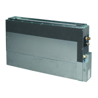
FXYC32K 2F01
2nd floor
office
A 1–00
FXYC63K 2F02
2nd floor
office
A (1–00)
FXYC40K 2F03
2nd floor
office
A (1–00)
FXYC63K 2F04
2nd floor
office
B 1–01
FXYC50K 2F05
2nd floor
office
B (1–01)
RSXY18KA
(PAC2)
Cool/Heat
selector:
Indoor unit
Low noise
operation
(L.N.O.P):
Individual control
Sequential start:
ON Defrost:
Earlier
FXYC32K 3F01
3rd floor
office
C 1–02
FXYC40K 3F02
3rd floor
office
C (1–02)
FXYC50K 3F03
3nd floor
office
C (1–02)
FXYC50K 3F04
3rd floor
office
D 1–03
Si33-102.book Page 10 Tuesday, June 26, 2001 3:18 PM
Все каталоги и инструкции здесь: http://splitoff.ru/tehn-doc.html
 Loading...