Test Operation SiE33-102
64 General Information
Note: Resetting of power supply switch is necessary after capacity setting.
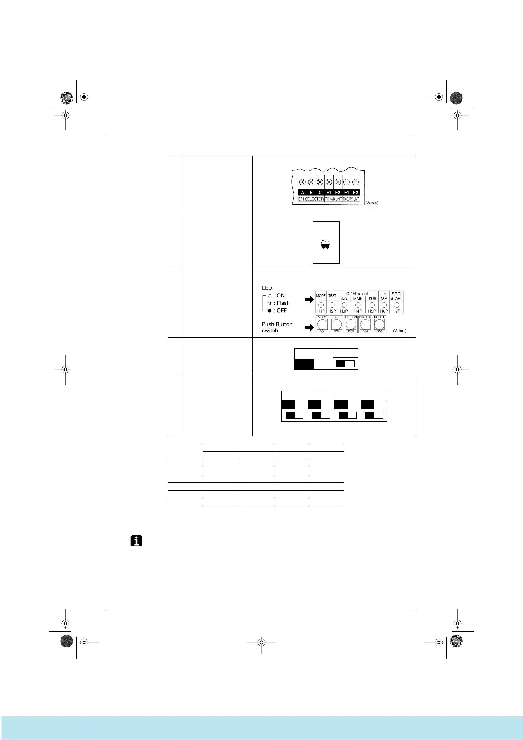
1 Transmission terminal
Indoor unit, Cool/Heat selector
Outdoor - Outdoor
2 Service monitor LED (Green)
3 Function setting mode switch
and LED
LED
4 Function of setting between
cooling and heating
5 Outdoor unit
Capacity setting switch
Switches for capacity setting when the outdoor unit PC board is replaced
to spare parts PC board.
Refer table below.
HAP
LED-A
SERV. MON.
(V0836)
C/H SELECT
IN/D
OUT/D
SS1
(V0838)
SS2
BDFH
SS3 SS4 SS5
ACEG
(V0848)
SS2 SS3 SS4 SS5
ABCDEFGH
RSXY16KA
RSXY18KA
RSXY20KA
RSXY24KA
RSXY26KA
RSXY28KA
RSXY30KA
Capacity setting table ↑
Position of dip switch
knob
Si33-102.book Page 64 Tuesday, June 26, 2001 3:18 PM
Все каталоги и инструкции здесь: http://splitoff.ru/tehn-doc.html
 Loading...