78 • Technical Specifications Xtium2-CLHS PX8 User's Manual
J3: Camera Link HS Connector
Note: The Camera Link HS camera connector is defined in the AIA document “Specifications of the
Camera Link HS Interface Standard for Digital Cameras and Frame Grabbers” version 1.0 RC5,
©2012 AIA. Typically there is no need to be concerned with the physical pinout of the connector or
cables. Refer to their site www.visiononline.org
for additional information.
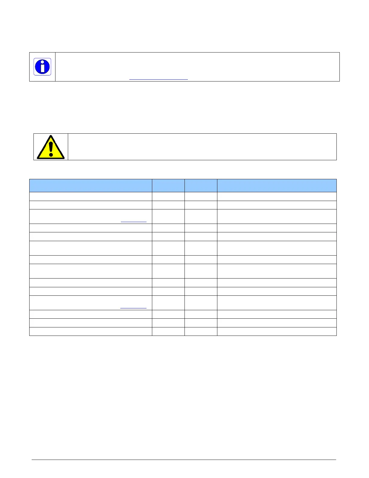
J1: External I/O Signals Connector (Female DH60-27P)
J4: Internal I/O Signals Connector (26-pin SHF-113-01-L-D-RA)
Warning: J1 and J4 have the same pinout assignment. Signals are routed to both connectors
directly from their internal circuitry. Therefore never connect both J1 and J4 to external devices
at the same time.
Description Pin # Pin # Description
Ground 1 15 General Input 3 (+)
RS-422 Shaft Encoder Phase A (-) 2 16 General Input 4 (+)
RS-422 Shaft Encoder Phase A (+)
(see note 3
)
3 17 General Input 4 (-)
Ground 4 18 General Input 3 (-)
RS-422 Shaft Encoder Phase B (-) 5 19 Power Output 5 Volts, 100mA max
RS-422 Shaft Encoder Phase B (+) 6 20 External Trigger Input 2 or
General Input 2 (-)
External Trigger Input 1/General Input 1 (-) 7 21 General Output 3
External Trigger Input 1/General Input 1 (+)
8 22 General Output 4
External Trigger Input 2/General Input 2 (+) 9 23 General Output 5
Ground 10 24 General Output 6
Strobe 1 / General Output 1
(See note 2
)
11 25 General Output 7
General Output 2 12 26 General Output 8
Ground 13 27 NC
Power Output 12 Volts, 350mA max 14