Xtium2-CLHS PX8 User's Manual Technical Specifications • 81
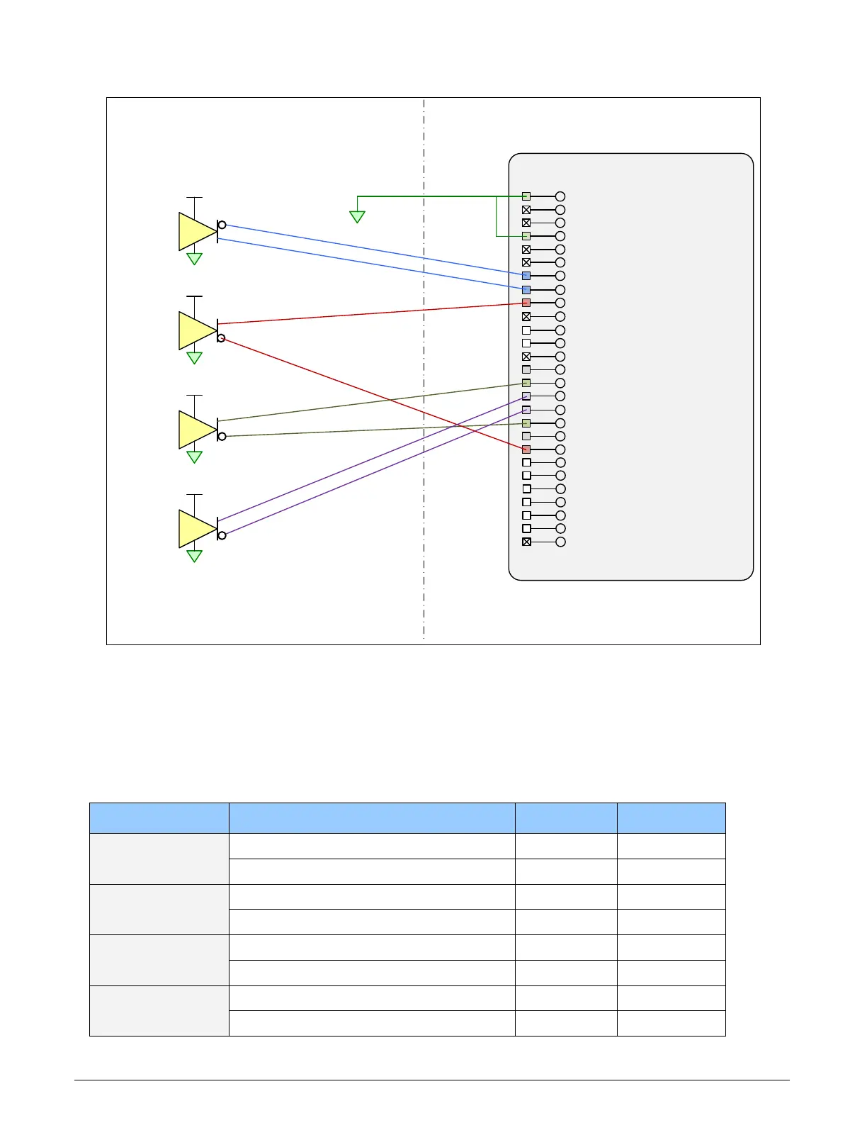
Block Diagram: Connecting External Drivers to General Inputs on J1
J1:
External Signals Connector
(DH60-27P)
Reserved
4
External Signals Xtium-CLHS
PX8
26
27
:
:
V (+)
3
V (+)
2
V (+)
1
V
(+)
Differential
Driver
User Signal
Ground
25 :
24 :
23 :
General Output 422 :
General Output 3
21 :
19
20
:
:
18 :
17
:
General Input 4
(+)16 :
General Input 3
(+)15 :
Power Output (12 Volts)14
:
Ground13 :
General Output
212 :
General Output
1 /
Strobe11 :
Ground10 :
General Input
2 /
Trigger 2
(+)
9 :
General Input 1
/
Trigger 1 (+)
8 :
7 :
Shaft Encoder B
(+)
6 :
Shaft Encoder B (-)5 :
Ground4
:
Shaft Encoder A (+)
3
:
Shaft Encoder A (
-
)
2
:
Ground
1
:
Differential
Driver
Differential
Driver
Differential
Driver
General Input
1
/ Trigger
1 (
-
)
General Input 4 (-
)
General Input 3 (-
)
Power Output (
5 Volts)
General Input 2 / Trigger
2 (-)
General Output 5
General Output 6
General Output 7
General Output 8
Figure 25:External Signals Connection Diagram
External Driver Electrical Requirements
The Xtium2-CLHS allows user selected (software programmable) input switching points to support
differential (RS-422) input signals and single ended (TTL, 12V or 24V) input signals. The following
table defines the external signal voltage requirements from the driver circuits connected to the
Xtium2 external inputs.
Input Level Description MIN MAX
RS-422
Output Voltage High (V
OH
)
2.4 V 13.0 V
Output Voltage Low (V
OL
)
-2.4 V -13.0 V
TTL
Output Voltage High (V
OH
)
2.4 V 5.5 V
Output Voltage Low (V
OL
)
0 V 0.8 V
12V
Output Voltage High (V
OH
)
9 V 13.2 V
Output Voltage Low (V
OL
)
0 V 3 V
24V
Output Voltage High (V
OH
)
18 V 26.4 V
Output Voltage Low (V
OL
)
0 V 6 V