Terminal Parameter Default
setting
Description
12, 13 – +24 V DC 24 V DC supply
voltage for digital
inputs and external
transducers.
Maximum output
current 200 mA for all
24 V loads.
18 Parameter 5-10
Terminal 18
Digital Input
[8] Start Digital inputs.
19 Parameter 5-11
Terminal 19
Digital Input
[10]
Reversing
32 Parameter 5-14
Terminal 32
Digital Input
[0] No
operation
33 Parameter 5-15
Terminal 33
Digital Input
[0] No
operation
27 Parameter 5-12
Terminal 27
Digital Input
[2] Coast
inverse
For digital input or
output. Default
setting is input.
29 Parameter 5-13
Terminal 29
Digital Input
[14] JOG
20 – – Common for digital
inputs and 0 V
potential for 24 V
supply.
37 – STO When not using the
optional STO feature,
a jumper wire is
required between
terminal 12 (or 13)
and terminal 37. This
set-up allows the
drive to operate with
factory default
programming values.
Table 10.6 Digital Input/Output Terminal Descriptions
Terminal Parameter Default
setting
Description
39 – – Common for analog
output.
42 Parameter 6-50
Terminal 42
Output
[0] No
operation
Programmable analog
output. 0–20 mA or
4–20 mA at a
maximum of 500 Ω.
Terminal Parameter Default
setting
Description
50 – +10 V DC 10 V DC analog
supply voltage for
potentiometer or
thermistor. 15 mA
maximum.
53 Parameter
group 6-1*
Analog Input 1
Reference Analog input. For
voltage or current.
Switches A53 and
A54 select mA or V.
54 Parameter
group 6-2*
Analog Input 2
Feedback
55 – – Common for analog
input.
Table 10.7 Analog Input/Output Terminal Descriptions
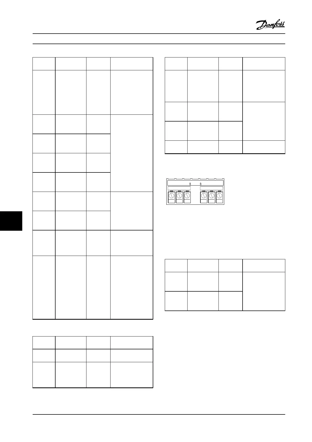
Relay terminals
RELAY 1 RELAY 2
01 02 03 04 05 06
130BF156.10
Figure 10.8 Relay 1 and Relay 2 Terminals
•
Relay 1 and relay 2. Location depends on drive
conguration. See the operating guide.
•
Terminals on built-in optional equipment. See the
instructions provided with the equipment option.
Terminal Parameter Default
setting
Description
01, 02, 03 Parameter 5-40
Function Relay
[0]
[0] No
operation
Form C relay output.
For AC or DC voltage
and resistive or
inductive loads.
04, 05, 06 Parameter 5-40
Function Relay
[1]
[0] No
operation
Table 10.8 Relay Terminal Descriptions
Electrical Installation Con...
VLT
®
AQUA Drive FC 202
162 Danfoss A/S © 01/2018 All rights reserved. MG22B222
1010

 Loading...


