Requirements related to the Ex-e motor
•
Ensure that the Ex-e motor is approved for
operation in hazardous zones (ATEX zone 1/21,
ATEX zone 2/22) with drives. The motor must be
certied for the specic hazardous zone.
•
Install the Ex-e motor in zone 1/21 or 2/22 of the
hazardous zone, according to motor approval.
NOTICE!
Install the drive outside the hazardous zone.
•
Ensure that the Ex-e motor is equipped with an
ATEX-approved motor overload protection device.
This device monitors the temperature in the
motor windings. If there is a critical temperature
level or a malfunction, the device switches o the
motor.
-
The VLT
®
PTC Thermistor Card MCB 112
option provides ATEX-approved
monitoring of motor temperature. It is a
prerequisite that the drive is equipped
with 3–6 PTC thermistors in series
according to DIN 44081 or 44082.
- Alternatively, an external ATEX-approved
PTC protection device can be used.
•
Sine-wave
lter is required when
- Long cables (voltage peaks) or increased
mains voltage produce voltages
exceeding the maximum allowable
voltage at motor terminals.
- Minimum switching frequency of the
drive does not meet the requirement
stated by the motor manufacturer. The
minimum switching frequency of the
drive is shown as the default value in
parameter 14-01 Switching Frequency.
Compatibility of motor and drive
For motors certied according to EN-60079-7, a data list
including limits and rules is supplied by the motor
manufacturer as a data sheet, or on the motor nameplate.
During planning, installation, commissioning, operation,
and service, follow the limits and rules supplied by the
manufacturer for:
•
Minimum switching frequency.
•
Maximum current.
•
Minimum motor frequency.
•
Maximum motor frequency.
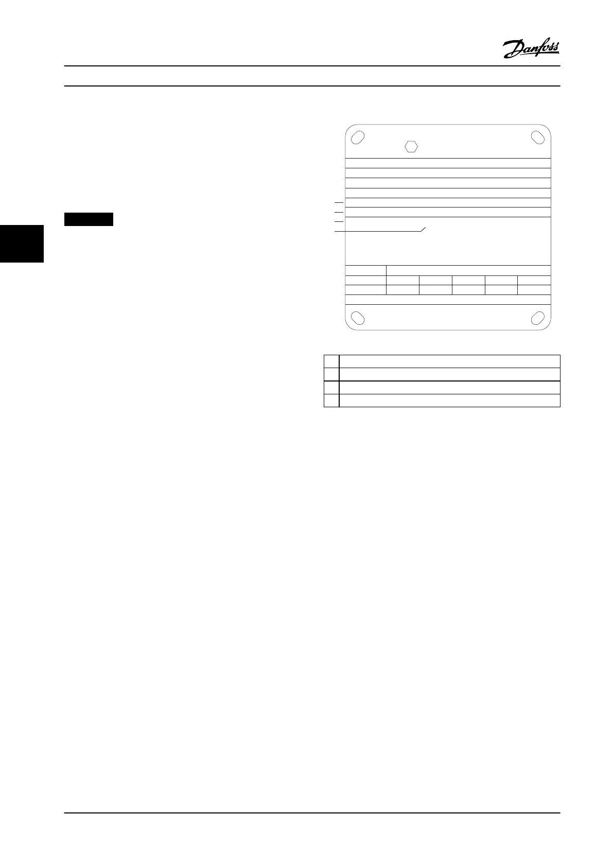
Figure 5.2 shows where the requirements are indicated on
the motor nameplate.
130BD888.10
CONVERTER SUPPLY
VALID FOR 380 - 415V FWP 50Hz
3 ~ Motor
MIN. SWITCHING FREQ. FOR PWM CONV. 3kHz
l = 1.5XI
M,N
tOL = 10s tCOOL = 10min
MIN. FREQ. 5Hz MAX. FREQ. 85 Hz
PWM-CONTROL
f [Hz]
Ix/I
M,N
PTC °C DIN 44081/-82
Manufacture xx
EN 60079-0
EN 60079-7
СЄ 1180 Ex-e ll T3
5 15 25 50 85
0.4 0.8 1.0 1.0 0.95
1
xЗ
2
3
4
1 Minimum switching frequency
2 Maximum current
3 Minimum motor frequency
4 Maximum motor frequency
Figure 5.2 Motor Nameplate showing Drive Requirements
When matching drive and motor, Danfoss species the
following extra requirements to ensure adequate motor
thermal protection:
•
Do not exceed the maximum allowed ratio
between drive size and motor size. The typical
value is I
VLT, n
≤2xI
m,n
•
Consider all voltage drops from drive to motor. If
the motor runs with lower voltage than listed in
the U/f characteristics, current can increase,
triggering an alarm.
For further information, see the application example in
chapter 12 Application Examples.
Product Features
VLT
®
AQUA Drive FC 202
22 Danfoss A/S © 01/2018 All rights reserved. MG22B222
55

 Loading...


