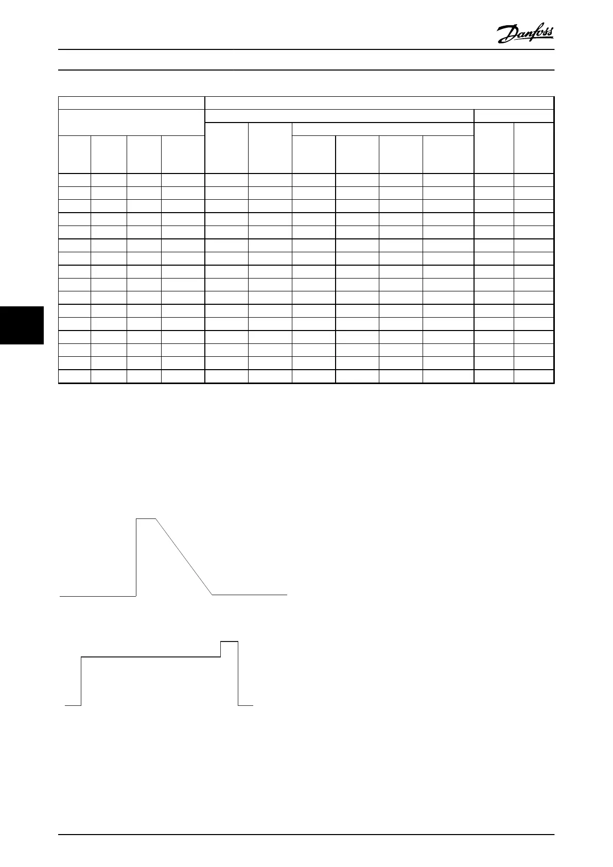
FC 302 Vertical braking 40% duty cycle
Frequency converter data
Brake resistor data Installation
R
rec
[Ω]
P
br.cont.
[kW]
Danfoss part number
Cable
cross
section
[mm
2
]
Thermo
relay
[A]
Mains
type
P
m
[kW]
R
min
[Ω]
R
br.nom
[Ω]
Wire IP54
Screw
terminal
IP21
Screw
terminal
IP65
Bolt
connection
IP20
T7 1.1 620 830 630 0.360 - 175u3108 175u3109 - 1.5 0.8
T7 1.5 513 600 570 0.570 - 175u3110 175u3111 - 1.5 1
T7 2.2 340 403 415 0.790 - 175u3112 175u3113 - 1.5 1.3
T7 3 243 292 270 1.130 - 175u3118 175u3119 - 1.5 2
T7 4 180 216 200 1.700 - 175u3122 175u3123 - 1.5 2.8
T7 5.5 130 156 145 2.200 - 175u3106 175u3107 - 1.5 3.7
T7 7.5 94 113 105 3.200 - 175u3132 175u3133 - 1.5 5.2
T7 11 69.7 76.2 72 4.200 - 175u3142 175u3143 - 1.5 7.2
T7 15 46.8 55.5 52 6.000 - - - 175u3242 2.5 10.8
T7 18.5 36.0 44.7 42 8.000 - - - 175u3243 2.5 13.9
T7 22 29.0 37.5 31 10.000 - - - 175u3244 4 18
T7 30 22.5 29.1 27 14.000 - - - 175u3201 10 23
T7 37 18.0 23.5 22 17.000 - - - 175u3202 10 28
T7 45 13.5 19.3 15.5 21.000 - - - 175u3205 16 37
T7 55 13.5 15.7 13.5 26.000 - - - 175u3209 16 44
T7 75 8.8 11.5 11 36.000 - - - 175u3212 25 57
Table 7.16 T7, Vertical Braking 40% Duty Cycle
Horizontal braking: Duty cycle 10% and maximum 120 s repetition rates according the reference brake profile. Average power corresponds to 6%.
Vertical braking: Duty cycle 40% and maximum 120 s repetition rates according the reference brake profile. Average power corresponds to 27%.
Cable cross-section: Recommended min. value based upon PVC-insulated copper cable, 30
°
C ambient temperature with normal heat dissipation.
All cabling must comply with national and local regulations on cable cross-sections and ambient temperature.
Thermal relay: Brake current setting of external thermal relay. All resistors have a built-in thermal relay switch N.C.
The IP54 is with 1,000 mm fixed unscreened cable. Vertical and horizontal mounting. Derating required by horizontal mounting.
IP21 & IP65 are with screw terminal for cable termination. Vertical and horizontal mounting. Derating required by horizontal mounting.
The IP20 is with bolt connection for cable termination. Floor mounting.
Illustration 7.2 Horizontal Loads
Illustration 7.3 Vertical Loads
How to Order
VLT
®
AutomationDrive FC 301/FC 302 Design Guide, 0.25-75 kW
98 MG33BF02 - Rev. 2013-12-20
77

 Loading...


