2
130BA709.11
1
LABEL
Remove jumper to activate Safe Stop
12
13
18
19
27
29
33
32
20
39
42
50
53
54
61
68
CAUTION:
SEE MANUAL / RCD and high leakage current
VOIR MANUAL / Fransk tekst
WARNING:
Stored charge / “Fransk tekst” (4 min.)
LISTED 76x1 134261
INDUSTRIAL CONTROL EQUIPMENT
SEE MANUAL FOR PREFUSE TUPE IN UL
APPLICATIONS
T/C : CIAXXXPT5B20BR1DBF00A00
P/N : XXXN1100 S/N: 012815G432
IN: 3x380-480V 50/60Hz 14.9A
OUT: 3x0-Uin 0-1000Hz 16.0A 11.1 kVA
CHASIS/IP20 Tamb Max 45C/113F
MADE IN DENMARK
9Ø
9Ø
Ø6
1
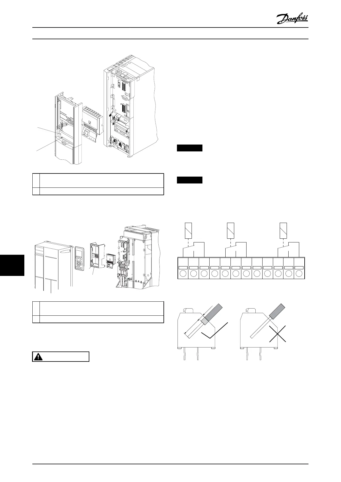
IMPORTANT ! The label MUST be placed on the LCP frame
as shown (UL approved).
2 Relay card
Illustration 11.8 Enclosure Types A2-A3-B3
2
130BA710.11
1
LABEL
Remove jumper to activate Safe Stop
13
12
18
19
27
32
38
2
28
42
39
53
50
5
61
6
9Ø
9Ø
DC-
DC+
1
IMPORTANT ! The label MUST be placed on the LCP frame
as shown (UL approved).
2 Relay card
Illustration 11.9 Enclosure Types A5-B1-B2-B4-C1-C2-C3-C4
WARNING
Warning Dual supply
How to add the Relay Card MCB 105 Option:
1. Disconnect power to the frequency converter.
2. Disconnect power to the live part connections on
relay terminals.
3. Remove the LCP, the terminal cover and the LCP
fixture from the frequency converter.
4. Fit the MCB 105 option in slot B.
5. Connect the control cables and fasten the cables
with the enclosed cable strips.
6. Make sure the length of the stripped wire is
correct (see Illustration 11.11).
7. Do not mix live parts (high voltage) with control
signals (PELV).
8. Fit the enlarged LCP fixture and enlarged
terminal cover.
9. Replace the LCP.
10. Connect power to the frequency converter.
11.
Select the relay functions in 5-40 Function Relay
[6-8], 5-41 On Delay, Relay [6-8] and 5-42 Off
Delay, Relay [6-8].
NOTICE
Array [6] is relay 7, array [7] is relay 8, and array [8] is
relay 9
NOTICE
To access RS-485 termination switch S801 or current/
voltage switches S201/S202, dismount the relay card (see
Illustration 11.8 and Illustration 11.9, position 2).
Relay 7
NC NCNC
Relay 9Relay 8
1 2 3 12
130BA162.10
754 6 8 9 10 11
Illustration 11.10 Relays
Illustration 11.11 Correct Wire Inserting
Options and Accessories
VLT
®
AutomationDrive FC 301/FC 302 Design Guide, 0.25-75 kW
158 MG33BF02 - Rev. 2013-12-20
1111
 Loading...


