•
•
Ensure that all drives in the torque sharing system use the same parameter settings.
Adjust the value in parameter 7-01 Speed PID Droop.
N O T I C E
Do not use overvoltage control when using the PID droop function (select [0] Disabled in parameter 2-17 Over-voltage Control).
N O T I C E
If the speed reference is lower than the value in parameter 7-01 Speed PID Droop, the drive makes the PID droop factor equal to
the speed reference.
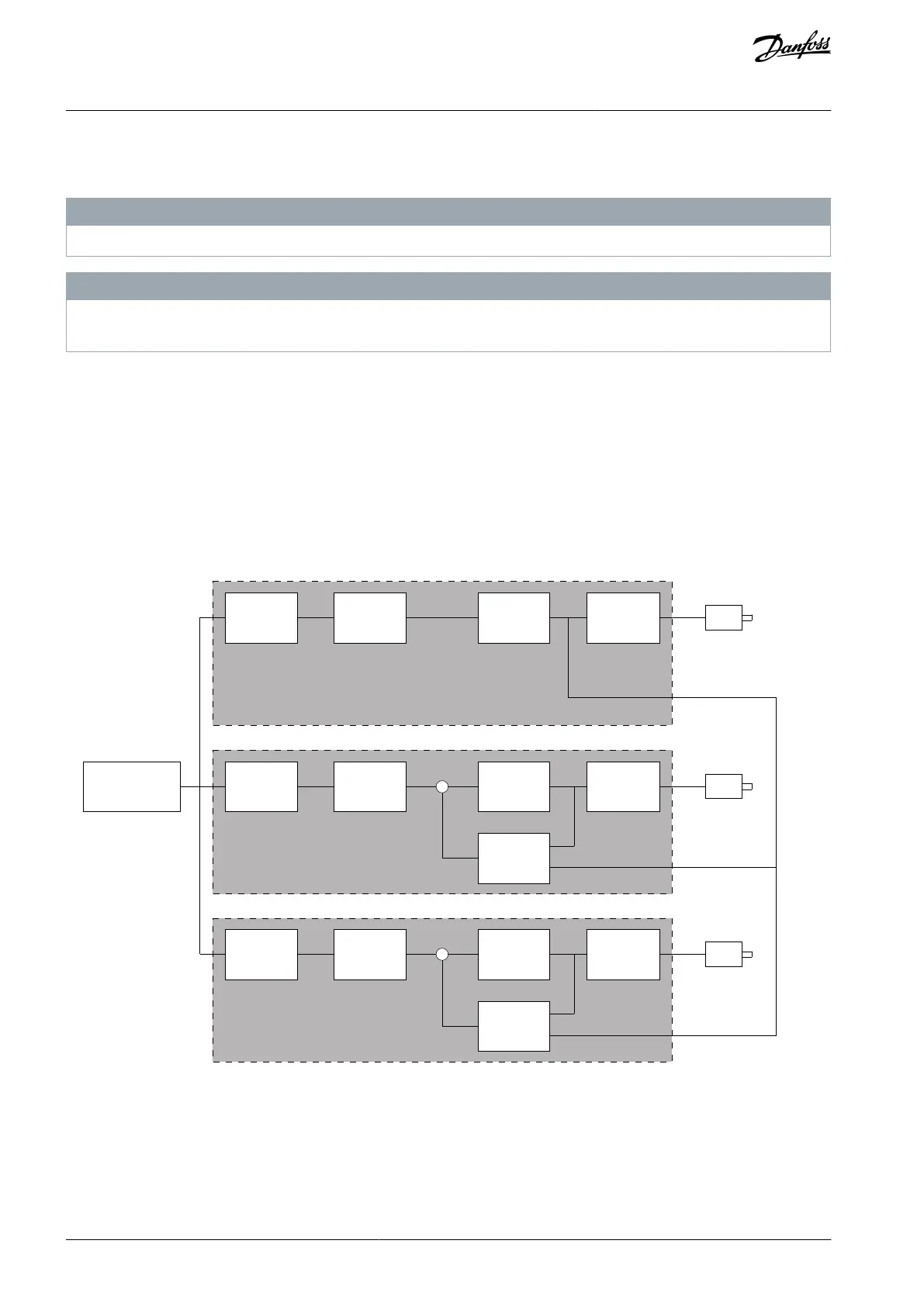
5.8.2 Speed Trim
The speed trim function is an add-on to the speed PID droop. The speed trim provides torque sharing with precise speed down to
0 RPM. The function requires wiring of analog signals.
In speed trim, the master drive runs normal speed PID without droop. The follower drives use the speed PID droop, but instead of
reacting on their own load, they compare their own load to the load of other drives in the system. The follower drives then use that
data as input for the speed PID droop. A setup with a single source, where the master drive sends information about torque to all
followers, is limited by the number of available analog outputs on the master drive. It is possible to use a cascade principle which
overcomes this limitation, but makes the control slower and less accurate. The master drive operates in speed mode. The follower
drives operate in speed mode with the speed trim. The trim function uses torque data from all drives in the system.
e30be998.11
Set-point
Calculation
External Set-point
Ramp
Droop
Speed
PID
Torque
PID
M2
M3
Drive 2
Drive 3
Set-point
Calculation
Ramp
Droop
Speed
PID
-
Set-point
Calculation
Ramp
Speed
PID
Torque
PID
M1
Drive 1
-
Torque
PID
Illustration 73: Speed Trim
The drawing shows a single-source setup where the master sends the torque signal to all followers. The number of available analog
outputs on the master limits this setup. To overcome the limitation of the number of analog outputs, use a cascade principle. The
cascade principle makes the control slower and less accurate compared with the setup using analog outputs.
AU275636650261en-000101 / 130R0334254 | Danfoss A/S © 2022.12
Parameter Descriptions
VLT AutomationDrive FC 301/302
Programming Guide

 Loading...


