•
•
N O T I C E
Only use ATEX Ex-e-approved motors for this function. See motor nameplate, approval certificate, datasheet, or contact motor
supplier.
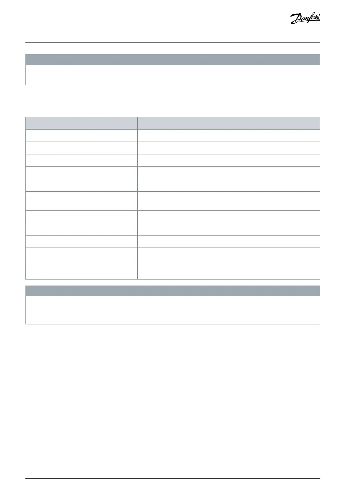
When controlling an Ex-e motor with increased safety, it is important to ensure certain limitations. The parameters that must be
programmed are presented in the following table.
Table 147: Parameters
Parameter 1-90 Motor Thermal Protection
Parameter 1-94 ATEX ETR cur.lim. speed reduction
Parameter 1-98 ATEX ETR interpol. points freq.
Parameter 1-99 ATEX ETR interpol points current
Parameter 1-23 Motor Frequency
Enter the same value as for parameter 4-19 Max Output Frequency.
Parameter 4-19 Max Output Frequency
Motor nameplate, possibly reduced for long motor cables, sine-wave filter, or
reduced supply voltage.
Parameter 4-18 Current Limit
Forced to 150% by 1-90 [20]
Parameter 5-15 Terminal 33 Digital Input
Parameter 5-19 Terminal 37 Safe Stop
Parameter 14-01 Switching Frequency
Check that the default value fulfills the requirement from the motor name-
plate. If not, use a sine-wave filter.
Parameter 14-26 Trip Delay at Inverter Fault
N O T I C E
Compare the minimum switching frequency requirement stated by the motor manufacturer to the minimum switching frequen-
cy of the drive, the default value in parameter 14-01 Switching Frequency. If the drive does not meet this requirement, use a sine-
wave filter.
More information about ATEX ETR thermal monitoring can be found in Application Note for FC 300 ATEX ETR Thermal Monitoring
Function.
5.2.10.5 Klixon
The Klixon type thermal circuit breaker uses a KLIXON® metal dish. At a predetermined overload, the heat caused by the current
through the disc causes a trip.
Using a digital input and 24 V as supply:
Example: The drive trips when the motor temperature is too high.
Parameter setup:
Set parameter 1-90 Motor Thermal Protection to [2] Thermistor Trip.
Set parameter 1-93 Thermistor Source to [6] Digital Input.
AU275636650261en-000101 / 130R0334110 | Danfoss A/S © 2022.12
Parameter Descriptions
VLT AutomationDrive FC 301/302
Programming Guide
 Loading...


