P
P
P
P
P
P
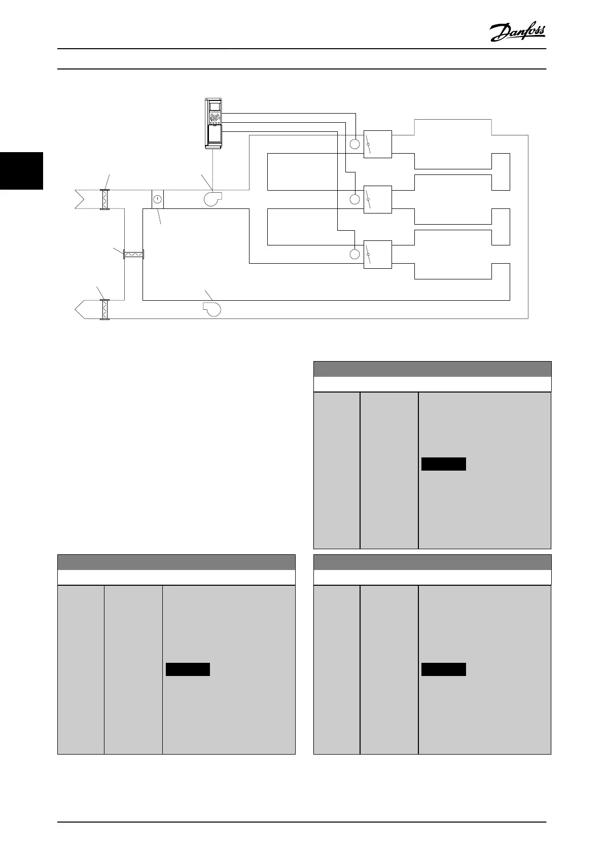
VAV
Box
Zone 1
Damper
Cooling/
heating coil
Supply
air fan
Return air fan
Damper
Damper
Zone 2
Zone 3
VAV
Box
VAV
Box
130BA353.10
Illustration 3.54 Example, Multi-zone, Single Setpoint
Example 2 – Multi-zone, multi-setpoint
The previous example illustrates the use of multi-zone,
multi-setpoint control. If the zones require dierent
pressures for each VAV box, each setpoint may be specied
in
•
Parameter 20-21 Setpoint 1.
•
Parameter 20-22 Setpoint 2.
•
Parameter 20-23 Setpoint 3.
By selecting [5] Multi-setpoint minimum in
parameter 20-20 Feedback Function, the PID controller
increases the fan speed if any one of the feedbacks is
below its setpoint. If all feedbacks are above their
individual setpoints, the PID controller decreases the fan
speed.
20-21 Setpoint 1
Range: Function:
0
ProcessCtrl
Unit*
[-999999.999
- 999999.999
ProcessCtrlUnit
]
Setpoint 1 is used in closed-loop
mode to enter a setpoint reference
that is used by the frequency
converter’s PID controller. See the
description of
parameter 20-20 Feedback Function.
NOTICE
The setpoint reference entered
here is added to any other
references that are enabled
(see parameter group 3-1*
References).
20-22 Setpoint 2
Range: Function:
0
ProcessCtrl
Unit*
[-999999.999
- 999999.999
ProcessCtrlUnit
]
Setpoint 2 is used in closed-loop
mode to enter a setpoint reference
for the PID controller. See the
description of
parameter 20-20 Feedback Function.
NOTICE
The setpoint reference entered
here is added to any other
references that are enabled
(see parameter group 3-1*
References).
20-23 Setpoint 3
Range: Function:
0
ProcessCtrl
Unit*
[-999999.999
- 999999.999
ProcessCtrlUnit
]
Setpoint 3 is used in closed-loop
mode to enter a setpoint reference
that may be used by the frequency
converter’s PID controller. See the
description of
parameter 20-20 Feedback Function.
NOTICE
The setpoint reference entered
here is added to any other
references that are enabled
(see parameter group 3-1*
References).
Parameter Descriptions
VLT
®
HVAC Drive FC 102
182 Danfoss A/S © 10/2019 All rights reserved. M0010001
33
 Loading...


