3.18.3 20-3* Feedback Adv. Conversion
In air-conditioning compressor applications, it is often
useful to control the system based on the temperature of
the refrigerant. However, it is generally more convenient to
directly measure its pressure. This parameter group allows
the frequency converter’s PID controller to convert
refrigerant pressure measurements into temperature values.
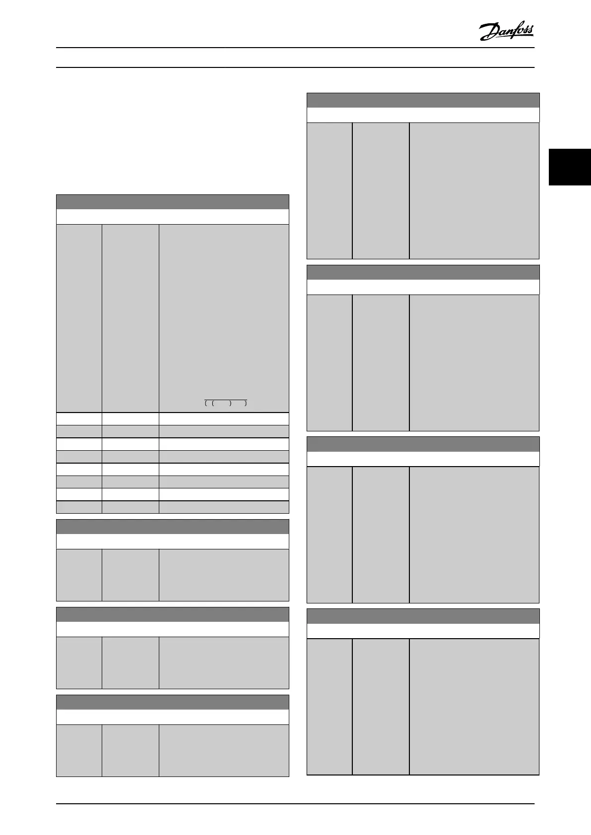
20-30 Refrigerant
Option: Function:
Select the refrigerant used in the
compressor application. This
parameter must be specied
correctly for the pressure to
temperature conversion to be
accurate. If the refrigerant used is
not listed in options [0] through [6],
select [7] User dened. Then, use
parameter 20-31 User Dened
Refrigerant A1, parameter 20-32 User
Dened Refrigerant A2, and
parameter 20-33 User Dened
Refrigerant A3 to provide A1, A2,
and A3 for the equation below:
Temperature =
A2
ln Pe + 1 − A1
− A3
[0] * R22
[1] R134a
[2] R404A
[3] R407C
[4] R410A
[5] R502
[6] R744
[7] User dened
20-31 User Dened Refrigerant A1
Range: Function:
10* [8 - 12 ] Use this parameter to enter the
value of coecient A1 when
parameter 20-30 Refrigerant is set to
[7] User dened.
20-32 User Dened Refrigerant A2
Range: Function:
-2250* [-3000 -
-1500 ]
Use this parameter to enter the
value of coecient A2 when
parameter 20-30 Refrigerant is set to
[7] User dened.
20-33 User Dened Refrigerant A3
Range: Function:
250* [200 - 300 ] Use this parameter to enter the
value of coecient A3 when
parameter 20-30 Refrigerant is set to
[7] User dened.
20-34 Duct 1 Area [m2]
Range: Function:
0.500 m2* [0.001 - 10
m2]
Used for setting the area of the air
ducts in connection with feedback
conversion pressure/velocity to
ow. The unit (m
2
) is determined by
the setting of
parameter 0-03 Regional Settings.
Fan 1 is used with feedback 1. In
case of ow dierence control, set
parameter 20-20 Feedback Function
to [1] Dierence, if ow fan 1 – ow
fan 2 is to be controlled.
20-35 Duct 1 Area [in2]
Range: Function:
750 in2* [1 - 15500
in2]
Used for setting the area of the air
ducts in connection with feedback
conversion pressure/velocity to
ow. The unit (in
2
) is determined by
the setting of
parameter 0-03 Regional Settings.
Fan 1 is used with feedback 1. In
case of ow dierence control, set
parameter 20-20 Feedback Function
to [1] Dierence, if ow fan 1 – ow
fan 2 is to be controlled.
20-36 Duct 2 Area [m2]
Range: Function:
0.500 m2* [0.001 - 10
m2]
Used for setting the area of the air
ducts in connection with feedback
conversion pressure/velocity to
ow. The unit (m
2
) is determined by
the setting of
parameter 0-03 Regional Settings.
Fan 2 is used with feedback 2. In
case of ow dierence control, set
parameter 20-20 Feedback Function
to [1] Dierence, if ow fan 1 – ow
fan 2 is to be controlled.
20-37 Duct 2 Area [in2]
Range: Function:
750 in2* [1 - 15500
in2]
Used for setting the area of the air
ducts in connection with feedback
conversion pressure/velocity to
ow. The unit (in
2
) is determined by
the setting of
parameter 0-03 Regional Settings.
Fan 2 is used with feedback 2. In
case of ow dierence control, set
parameter 20-20 Feedback Function
to [1] Dierence, if ow fan 1 – ow
fan 2 is to be controlled.
Parameter Descriptions Programming Guide
M0010001 Danfoss A/S © 10/2019 All rights reserved. 183
3 3
 Loading...


