[17] Preset ref bit
1
Enables a choice between 1 of the 8 preset
references according to Table 3.13.
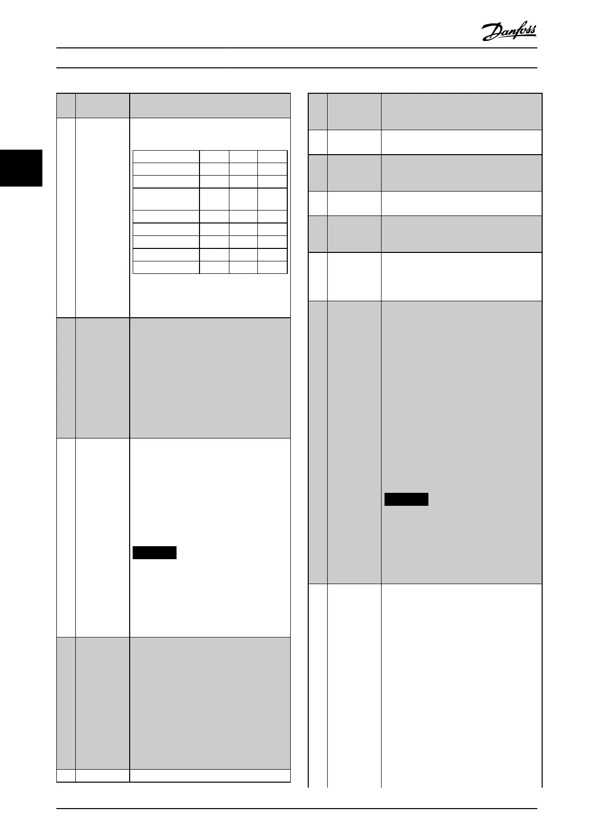
[18] Preset ref bit
2
Enables a choice between 1 of the 8 preset
references according to Table 3.13.
Preset ref. bit 2 1 0
Preset ref. 0 0 0 0
Preset ref. 1 0 0 1
Preset ref. 2 0 1 0
Preset ref. 3 0 1 1
Preset ref. 4 1 0 0
Preset ref. 5 1 0 1
Preset ref. 6 1 1 0
Preset ref. 7 1 1 1
Table 3.13 Digital Inputs Preset Reference
Bit
[19] Freeze ref Freezes the actual reference. The frozen
reference is now the point of enable/
condition for speed up and speed down to
be used. If speed up/down is used, the
speed change always follows ramp 2
(parameter 3-51 Ramp 2 Ramp Up Time and
parameter 3-52 Ramp 2 Ramp Down Time) in
the range 0 – parameter 3-03 Maximum
Reference. (For closed loop, see
parameter 20-14 Maximum Reference/Feedb.).
[20] Freeze output Freezes the actual motor frequency (Hz). The
frozen motor frequency is now the point of
enable/condition for Speed up and Speed
down to be used. If speed up/down is used,
the speed change always follows ramp 2
(parameter 3-51 Ramp 2 Ramp Up Time and
parameter 3-52 Ramp 2 Ramp Down Time) in
the range 0 – parameter 1-23 Motor
Frequency.
NOTICE
When Freeze output is active, the
frequency converter cannot be
stopped via a low [13] start signal.
Stop the frequency converter via a
terminal programmed for [2] Coasting
inverse or [3] Coast and reset, inverse.
[21] Speed up Select [21] Speed up and [22] Speed down if
digital control of the up/down speed is
desired (motor potentiometer). Activate this
function by selecting either [19] Freeze ref or
[20] Freeze output. When speed up/down is
activated for less than 400 ms, the resulting
reference is increased/decreased by 0.1%. If
speed up/down is activated for more than
400 ms, the resulting reference follows the
setting in ramping up/down parameter 3-
x1/3-x2.
[22] Speed down Same as [21] Speed up.
[23] Set-up select
bit 0
Selects 1 of the 4 setups. Set
parameter 0-10 Active Set-up 0-10 to [9] Multi
Set-up.
[24] Set-up select
bit 1
Same as [23] Set-up select bit 0.
[32] Pulse input Select [32] Pulse input when using a pulse
sequence as either reference or feedback.
Scaling is done in parameter group 5-5*.
[34] Ramp bit 0 Select which ramp to use. Logic 0 selects
ramp 1, while logic 1 selects ramp 2.
[36] Mains failure
inverse
Activates the function selected in
parameter 14-10 Mains Failure. Mains failure
is active in the logic 0 situation.
[37] Fire mode A signal applied puts the frequency
converter into Fire mode and all other
commands are disregarded. See parameter
group 24-0* Fire Mode.
[52] Run
Permissive
The input terminal, for which the run
permissive has been programmed, must be
logic 1 before a start command can be
accepted. Run permissive has a logic AND
function related to the terminal, which is
programmed for [8] Start, [14] Jog, or [20]
Freeze Output. To start running the motor,
both conditions must be fullled. If Run
Permissive is programmed on multiple
terminals, [52] Run permissive needs only be
logic 1 on 1 of the terminals to carry out
the function. The digital output signal for
Run Request ([8] Start, [14] Jog or [20] Freeze
output) programmed in parameter group 5-3*
Digital Outputs or parameter group 5-4*
Relays, is not aected by run permissive.
NOTICE
If no run permissive signal is applied,
but either Run, Jog, or Freeze
commands are activated, the status
line in the display shows either Run
Requested, Jog Requested, or Freeze
Requested.
[53] Hand start A signal applied puts the frequency
converter into Hand mode as if [Hand On]
was pressed on the LCP and a normal stop
command is overridden. If disconnecting the
signal, the motor stops. To make any other
start commands valid, another digital input
must be assigned to [54] Auto Start, and a
signal applied to this. The [Hand On] and
[Auto On] keys on the LCP have no impact.
The [O] key on the LCP overrides [53] Hand
Start and [54] Auto Start. Press either [Hand
On] or [Auto On] to make [53] Hand Start
and [54] Auto Start active again. If there is
no signal on neither [53] Hand Start nor [54]
Auto Start, the motor stops regardless of any
normal start command applied. If signals are
applied to both [53] Hand Start and [54]
Parameter Descriptions
VLT
®
HVAC Drive FC 102
88 Danfoss A/S © 10/2019 All rights reserved. M0010001
33
 Loading...


