to install. The Danfoss frequency converter solution
reduces
energy
consumption
with more than 50% and is
easy to install.
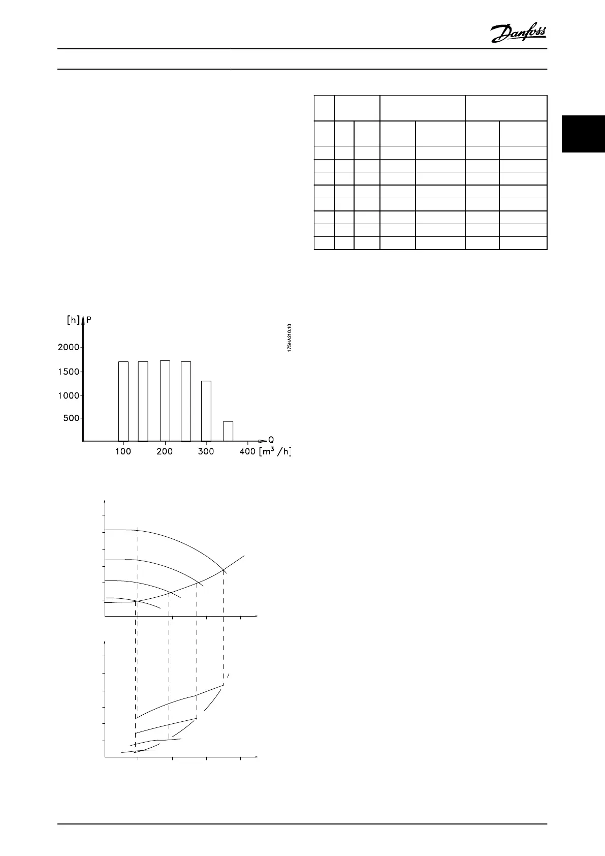
2.5.5 Example with Varying Flow over 1
Year
This example is calculated based on pump characteristics
obtained
from
a
pump datasheet.
The result obtained shows energy savings in excess of 50%
at the given flow distribution over a year. The pay back
period depends on the price per kWh and price of
frequency converter. In this example it is less than a year
when compared with valves and constant speed.
Energy savings
P
shaft
=P
shaft output
Illustration 2.6 Flow Distribution over 1 Year
175HA209.11
60
50
40
30
20
10
H
s
0 100 200 300 400
(mwg)
B
C
A
750rpm
1050rpm
1350rpm
1650rpm
0
10
20
30
(kW)
40
50
60
200100 300
(m
3
/h)
(
m
3
/h)
400
750rpm
1050rpm
1350rpm
1650rpm
P
shaft
C
1
B
1
A
1
Illustration 2.7
m
3
/
h
Distribution Valve regulation Frequency Converter
control
% Hours Power Consump-
tion
Power Consump-
tion
A
1
- B
1
kWh A
1
- C
1
kWh
350 5 438 42.5 18.615 42.5 18.615
300 15 1314 38.5 50.589 29.0 38.106
250 20 1752 35.0 61.320 18.5 32.412
200 20 1752 31.5 55.188 11.5 20.148
150 20 1752 28.0 49.056 6.5 11.388
100 20 1752 23.0 40.296 3.5 6.132
Σ
100 8760 275.064 26.801
Table 2.5
2.5.6 Better Control
If a frequency converter is used for controlling the flow or
pressure
of a system, improved control is obtained.
A frequency converter can vary the speed of the fan or
pump, obtaining variable control of flow and pressure.
Furthermore, a frequency converter can quickly adapt the
speed of the fan or pump to new flow or pressure
conditions in the system.
Simple control of process (Flow, Level or Pressure) utilizing
the built-in PI control.
2.5.7 Star/Delta Starter or Soft-starter not
Required
When larger motors are started, it is necessary in many
countries to use equipment that limits the start-up current.
In more traditional systems, a star/delta starter or soft-
starter is widely used. Such motor starters are not required
if a frequency converter is used.
Safety and Conformity
VLT
®
Micro Drive FC 51 Design Guide
MG02K202 - VLT
®
is a registered Danfoss trademark
15
2 2
Buy: www.ValinOnline.com | Phone 844-385-3099 | Email: CustomerService@valin.com

 Loading...


