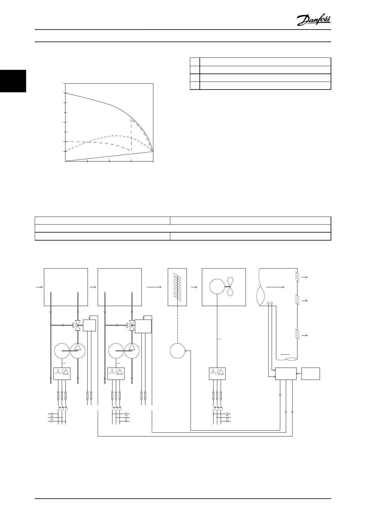
As illustrated in Illustration 2.8, a frequency converter does
not consume more than rated current.
Full load
% Full load current
& speed
500
100
0
0 12,5 25 37,5 50Hz
200
300
400
600
700
800
4
3
2
1
175HA227.10
Illustration 2.8
1
VLT
®
Micro Drive
2 Star/delta starter
3 Soft-starter
4 Start directly on mains
Table 2.6
2.5.8 Using a Frequency Converter Saves
Money
Example 2.5.9 Without a Frequency Converter shows that a
lot of equipment is not required when a frequency
converter is used. It is possible to calculate the cost of
installing the two different systems. In the example, the
two systems can be established at roughly the same price.
2.5.9 Without a Frequency Converter
D.D.C.=Direct Digital Control E.M.S.=Energy Management system
V.A.V.=Variable Air Volume
Sensor P=Pressure Sensor T=Temperature
Table 2.7 Fan System made in the Traditional Way
M
- +
M
M
x6 x6
x6
175HA205.12
Valve
posi-
tion
Starter
Fuses
LV
supply
P.F.C
Flow
3-Port
valve
Bypass
Return
Control
Supply
air
V.A.V
outlets
Duct
P.F.C
Mains
Fuses
Starter
Bypass
supply
LV
Return
valve
3-Port
Flow
Control
Valve
posi-
tion
Starter
Power
Factor
Correction
Mains
IGV
Mechanical
linkage
and vanes
Fan
Motor
or
actuator
Main
B.M.S
Local
D.D.C.
control
Sensors
PT
Pressure
control
signal
0/10V
Temperature
control
signal
0/10V
Control
Mains
Cooling section Heating section
Fan sectionInlet guide vane
Pump Pump
Illustration 2.9
Safety and Conformity
VLT
®
Micro Drive FC 51 Design Guide
16 MG02K202 - VLT
®
is a registered Danfoss trademark
22
Buy: www.ValinOnline.com | Phone 844-385-3099 | Email: CustomerService@valin.com

 Loading...


