3.2.1 RS232 Interface
The main serial interface is used in this case for point-to-point connections; it handles
communication with the host computer and allows both transmission of code data and
configuring the scanner. This is the default setting.
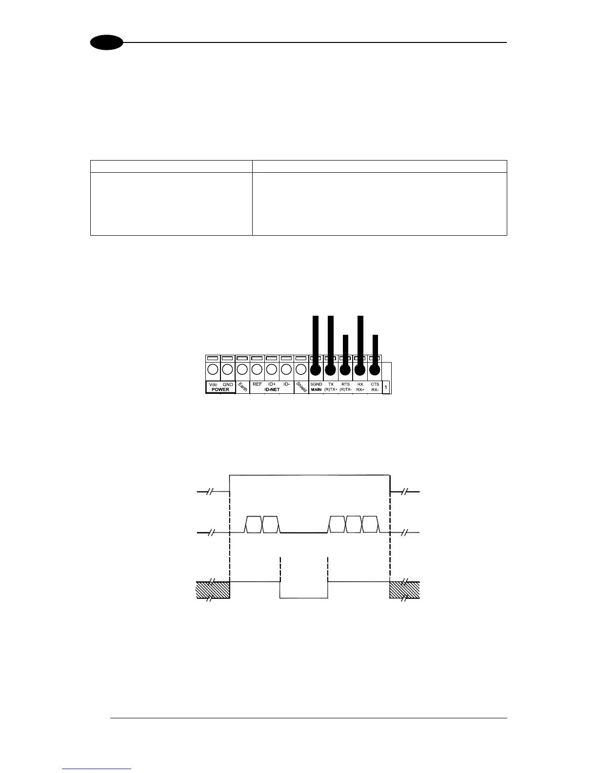
The following pins are used for RS232 interface connection:
It is always advisable to use shielded cables. If the shield is tied to ground at the Host, then
leave it floating at the CBX. If it is floating at the Host then tie it to Shield at the CBX. The
overall maximum cable length must be less than 15 m (50 ft).
Figure 16 – RS232 Main Interface Connections Using Hardware Handshaking
START
OF
TRANSMISSION
END
OF
TRANSMISSION
+ V
RTS
- V
+ V
TX DATA
- V
+ V
CTS
- V
DATA
TRANSMISSION
DATA
TRANSMISSION
C1
C2
C4
C3
C5
TRANSMISSION
STOPPED
ENABLED
DISABLED
ENABLED
IDLE
IDLE
Figure 17 - RS232 Control Signals
The RTS and CTS signals control data transmission and synchronize the connected devices.
If the RTS/CTS handshaking protocol is enabled, the DS8100A activates the RTS output to
indicate a message is to be transmitted. The receiving unit activates the CTS input to enable
the transmission.