4.3 AUXILIARY INTERFACE
The auxiliary serial interface is used exclusively for RS232 point-to-point connections. It is
principally used for scanner configuration from a laptop PC but is also available for LOCAL
ECHO to a monitoring PC or for Pass through layouts. This interface is active when the Data
Tx parameter is enabled. The overall maximum cable length should not exceed 15 m (50 ft).
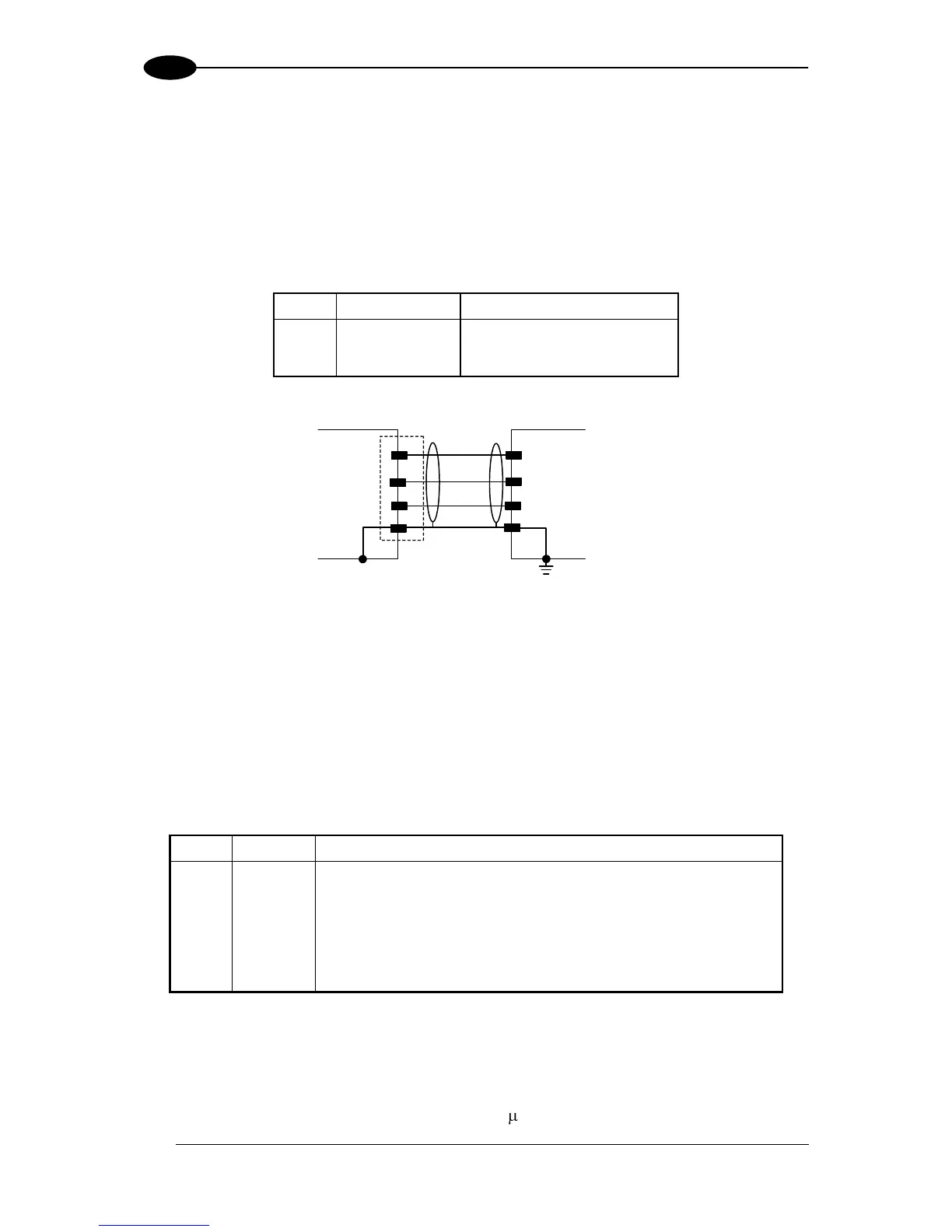
The following pins of the 26-pin connector are used for RS232 full-duplex interface
connection:
Figure 51 - RS232 Auxiliary Interface Connections
4.4 INPUTS
There are four optocoupled polarity insensitive inputs available on the 26-pin connector of
the DS8100A scanner: Input 1 (External Trigger/PS), Input 2 (Encoder), Input 3 and 4
generic inputs:
The electrical features of these inputs are:
Maximum voltage 30 Vdc
Maximum current all Inputs: 12 mA
External Trigger (polarity insensitive) for PS
External Trigger (polarity insensitive) for PS
Input Signal 2 (polarity insensitive) for Encoder
Input Signal 2 (polarity insensitive) for Encoder
Input Signal 3 (polarity insensitive)
Input Signal 4 (polarity insensitive)
Common Reference of Input 3 and Input 4 (polarity insensitive)
The active state of all the inputs is selected in software (open or closed). Refer to the
Genius™ Help On Line.
All inputs are optocoupled, polarity insensitive, and driven by a constant current generator;
the command signal is filtered through an anti-disturbance circuit which generates a
debouncing delay which can be set to 5 ms or 500 s. In particular, I1 for PS, I3 and I4 share