3.3 AUXILIARY RS232 INTERFACE
The auxiliary serial interface is used exclusively for RS232 point-to-point connections. It is
principally used for scanner configuration from a laptop PC but is also available for LOCAL
ECHO to a monitoring PC or for Pass through layouts. This interface is active when the Data
Tx parameter is enabled.
The parameters relative to the aux interface (baud rate, data bits, etc.) can be defined using
the Genius™ utility program or Genius™ based Host Mode Programming installed from the
CD-ROM.
The 9-pin female Auxiliary Interface connector inside the CBX is the preferred connector for
device configuration or temporary communication monitoring.
Figure 22 - 9-pin female connector
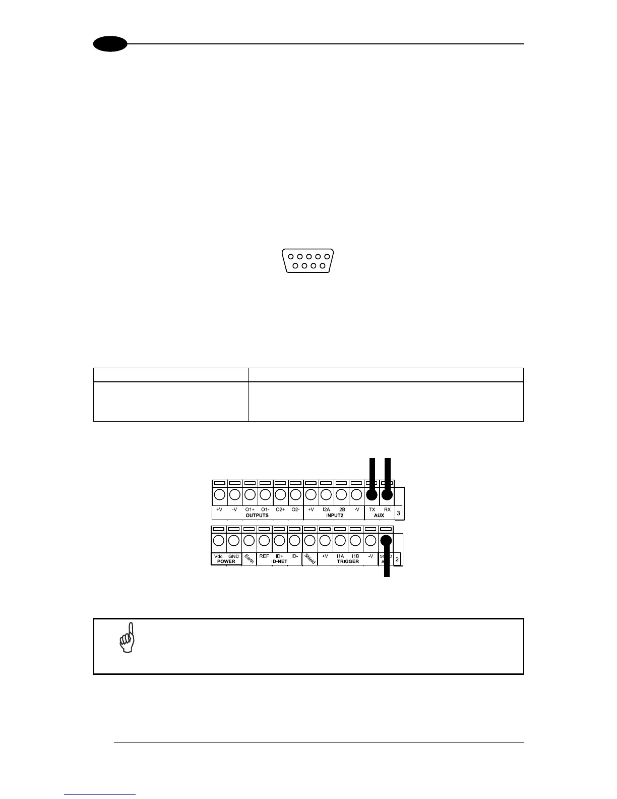
If permanent system wiring is required, the following pins are used to connect the RS232
auxiliary interface. The overall maximum cable length should not exceed 15 m (50 ft). In this
case it is advisable to use shielded cables. If the shield is tied to ground at the Host, then
leave it floating at the CBX. If it is floating at the Host then tie it to Shield at the CBX.
Auxiliary Interface Receive Data
Auxiliary Interface Transmit Data
Auxiliary Interface Reference
Figure 23 - RS232 Auxiliary Interface Connections
Do not connect the Aux Interface to the CBX spring clamp connectors and
the 9-pin connector simultaneously.