EasyManuals Logo
Home>Datalogic>Barcode Reader>DS8100A

Datalogic DS8100A User Manual

Datalogic DS8100A
141 pages
To Next Page IconTo Next Page
To Previous Page IconTo Previous Page
Page #61 background imageLoading...
Page #61 background image
CUSTOM CABLE ELECTRICAL CONNECTIONS
47
4
DS8100A
USER INTERFACE
Vext
100 Vdc max
A/B
B/A
Figure 59 Output 3 Interface
The command signals are filtered and generate a delay of about 50 µs for Output 1 and 2
and 1 ms for Output 3.
4.6 USER INTERFACE
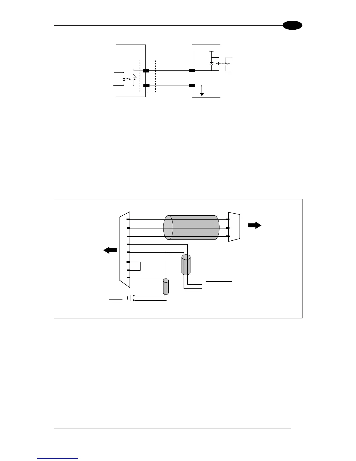
How To Build A Simple Interface Test Cable:
The following wiring diagram shows a simple test cable including power, external
(push-button) trigger and PC RS232 COM port connections.
26-pin D-sub female
23
20
GND
RXAUX
TXAUX
21
DS8100A
25
13
GND
VS
9-pin D-sub female
GND
TX
RX
PC
2
3
5
18
9
EXT TRIG A
VS
Power Supply
VS (20 30 VDC)
Power GND
Trigger
EXT TRIG B
19
Test Cable for DS8100A

Table of Contents

Questions and Answers:

Question and Answer IconNeed help?

Do you have a question about the Datalogic DS8100A and is the answer not in the manual?

Datalogic DS8100A Specifications

General IconGeneral
BrandDatalogic
ModelDS8100A
CategoryBarcode Reader
LanguageEnglish

Related product manuals