EasyManuals Logo

Datalogic DS8100A User Manual

Datalogic DS8100A
141 pages
To Next Page IconTo Next Page
To Previous Page IconTo Previous Page
Page #62 background imageLoading...
Page #62 background image
DS8100A REFERENCE MANUAL
48
5
5 LONWORKS CONNECTIONS
A1
A2
1
15
scanner side
external view
A1
A2
1
15
OUTPUT (female)
INPUT (male)
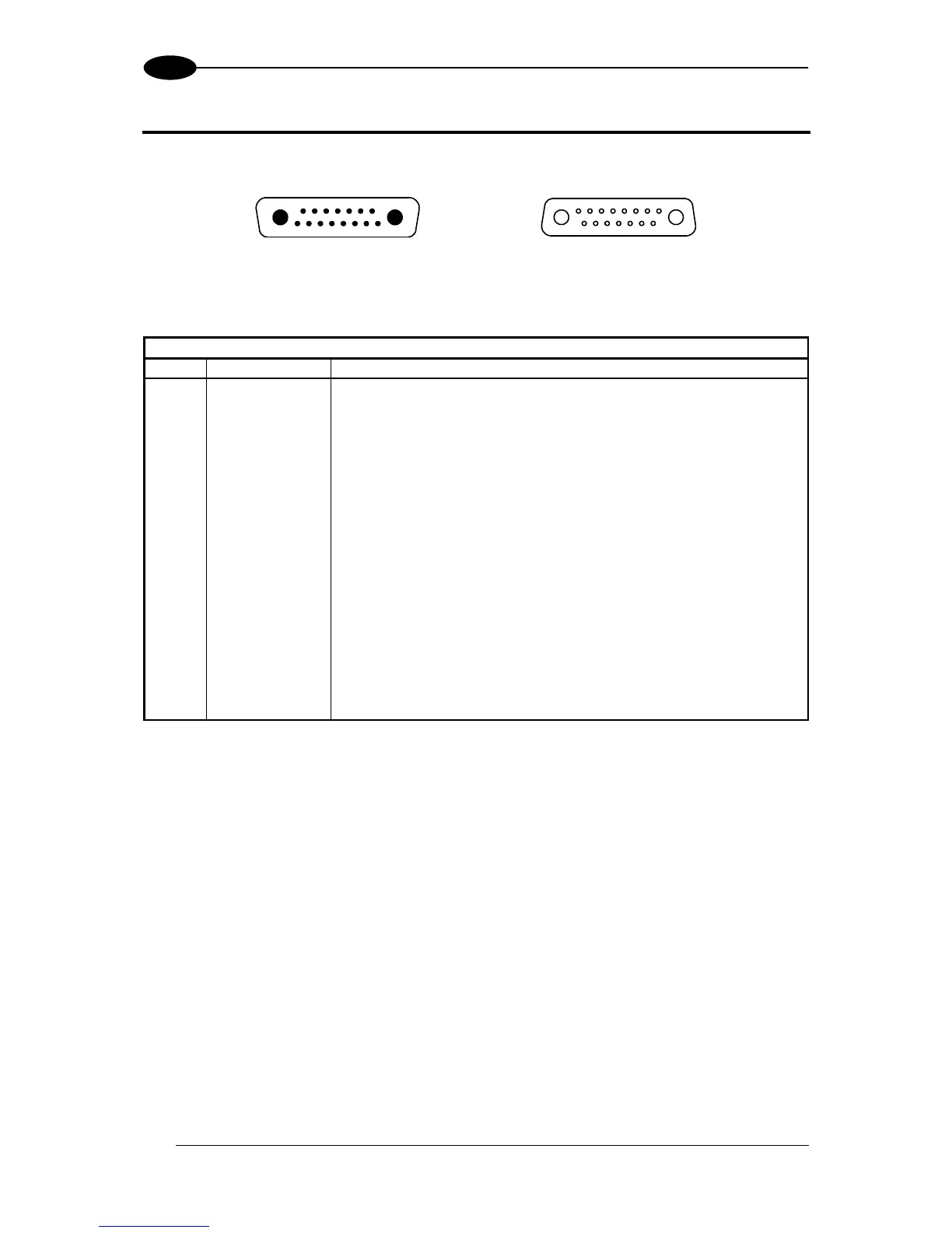
Figure 60 - Lonworks INPUT/OUTPUT Connectors
The following pinout is valid for the INPUT connector as well as for the OUTPUT connector.
Lonworks INPUT/OUTPUT 17-pin Connector Pinout
Pin
Name
Function
A1
GND
supply voltage (negative pin)
A2
VS
supply voltage 20 to 30 vdc (positive pin)
1
CHASSIS
Cable shield A internally connected by capacitor to chassis
2
n.c.
Not connected
3
CHASSIS
Cable shield B internally connected by capacitor to chassis
4
n.c.
Not connected
5
n.c.
Not connected
6
n.c.
Not connected
7
VS_I/O
Supply voltage of I/O circuit
8
Lon A+
Lonworks a line (positive pin)
9
Lon A-
Lonworks a line (negative pin)
10
Lon B+
Lonworks b line (positive pin)
11
Lon B-
Lonworks b line (negative pin)
12
SYS_I/O
System signal
13
SYS_ENC_I/O
System signal
14
Reserved
Internally connected
15
Ref_I/O
Reference voltage of I/O circuit

Table of Contents

Questions and Answers:

Question and Answer IconNeed help?

Do you have a question about the Datalogic DS8100A and is the answer not in the manual?

Datalogic DS8100A Specifications

General IconGeneral
BrandDatalogic
ModelDS8100A
CategoryBarcode Reader
LanguageEnglish

Related product manuals