the same value which usually corresponds to 5 ms when using a photoelectric sensor, while
I2 is set to 500 s when this input is used for the Encoder. The maximum Encoder frequency
is 2 kHz.
Input 1 (External Trigger/PS) is used in the On-Line and PackTrack™ operating Modes and
tells the scanner to scan for a code. The yellow Phase On LED (Figure C, 3) which refers to
Input 1 is on only when current flows through the input circuit and therefore when the active
state of this input is set to "active open", the LED lights up when the input corresponds to
OFF.
Input 2 is normally used for the Encoder input. In PackTrack™ mode, it detects the conveyor
speed.
Inputs 3 and 4 can be used as the stop signal for the reading phase.
The debouncing delay value can be changed through the software parameter Debouncing for
Input x, see the "6-8 K Software Configuration Parameter Guide” or Help file.
Powering Inputs
Input devices can be supplied by either scanner power (Vdc and GND) or external power
supplies (Vext).
Electrical isolation between the input command logic and the scanner is maintained when
powering the input devices from an external supply voltage (Vext).
The driving logic of the input signals may be powered, for convenience, with the voltage
supply between pins 9 (Vdc) and 23 (GND) of the 26-pin I/O connector. In this case,
however, the device is no longer electrically isolated. The voltage available on the 26-pin I/O
connector, is physically the same as used to power the scanner.
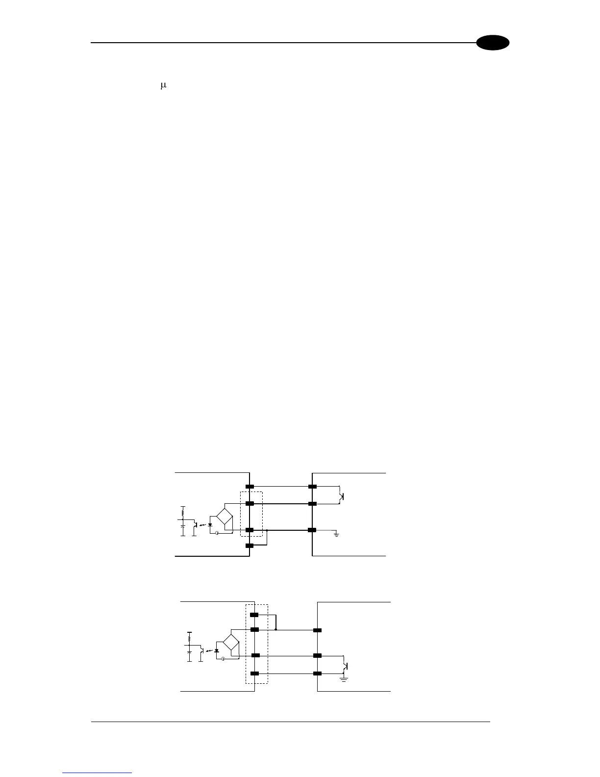
INPUT 1 - 2 CONNECTIONS USING DS8100A POWER