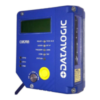
The details of the connector pins are indicated in the following table:
Figure 43 - 26-pin Connector
DS8100A 26-pin D-sub Connector Pinout
Chassis - internally connected to GND
Cable shield connected to chassis
Receive Data of Auxiliary RS232 (referred to GND)
Transmit Data of Auxiliary RS232 (referred to GND)
Configurable Digital Output 1 - positive pin
Configurable Digital Output 1 - negative pin
Configurable Digital Output 2 - positive pin
Configurable Digital Output 2 - negative pin
Configurable Digital Output 3 - polarity insensitive
Configurable Digital Output 3 - polarity insensitive
External Trigger (polarity insensitive) for PS
External Trigger (polarity insensitive) for PS
Input Signal 2 (polarity insensitive) for Encoder
Input Signal 2 (polarity insensitive) for Encoder
Input Signal 3 (polarity insensitive)
Input Signal 4 (polarity insensitive)
Common reference of Input 3 and Input 4 (polarity insensitive)
Power Supply Input Voltage +
Power Supply Input Voltage -
Main Interface Connector Pinout
* Do not leave floating, see par. 4.2.2 for connection details.
 Loading...


