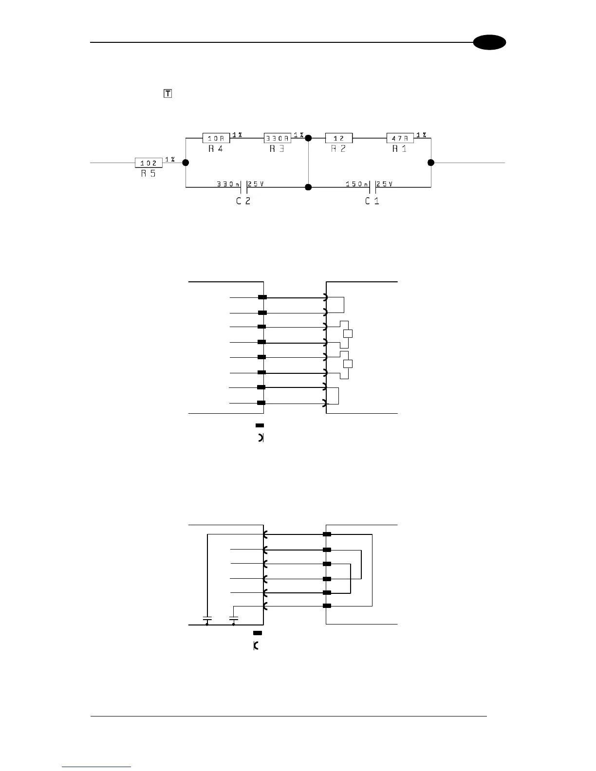
The following diagrams represent different network terminations using either the BTK-8102
Lonworks terminator or the BTK-8100 bus return. In Figure 65 the BTK-8102 terminator is
indicated by the element, while the figure below shows its electrical circuit in details:
Figure 64 – BTK-8102 Electrical Circuit
The diagram below represents the termination of the double Lonworks line of a DS8100A
working as master by means of the BTK-8102.
Figure 65 – DS8100A Master Termination
The diagram below represents the Lonworks bus return of a DS8100A working as slave by
means of the BTK-8100.