EasyManuals Logo

Datalogic DS8100A User Manual

Datalogic DS8100A
141 pages
To Next Page IconTo Next Page
To Previous Page IconTo Previous Page
Page #71 background imageLoading...
Page #71 background image
TYPICAL LAYOUTS
57
7
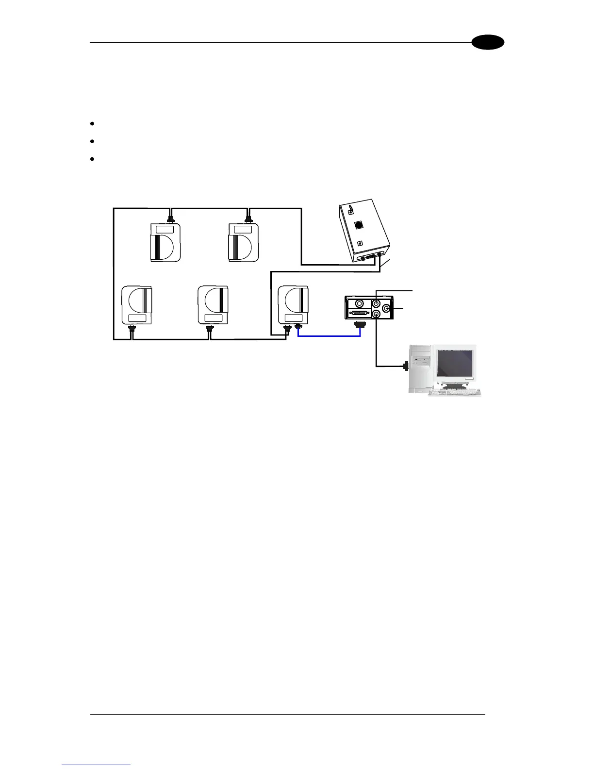
The following image shows a system consisting of five readers where the external signals
(trigger, encoder, serial to host, etc.) are connected to the master through the CBX100.
The system is powered by the PWR-240 where:
the master is connected through CAB-86xx, which also provides bus termination
the last slave is connected through CAB-83xx, which also provides bus return.
the master and all slaves are connected together through the CAB-81xx cables
* P.S. (Presence Sensor) connected to Input 1 (External Trigger/PS) input.
** CBX100 jumper set to accept scanner power.
*** Encoder connected to Input 2 (Encoder) input.
Figure 74 Small Synchronized Network with more than 2 Readers and Single Power Unit
CBX100**
Local Host
Master
Slave 1
Slave 2
Slave 3
PWR-240
P.S.*
CAB-81xx
CAB-F0x
CAB-81xx
CAB-81xx
Slave 4
CAB-86xx
CAB-81xx
CAB-83xx
Encoder***

Table of Contents

Questions and Answers:

Question and Answer IconNeed help?

Do you have a question about the Datalogic DS8100A and is the answer not in the manual?

Datalogic DS8100A Specifications

General IconGeneral
BrandDatalogic
ModelDS8100A
CategoryBarcode Reader
LanguageEnglish

Related product manuals