Technical Specifications
242 QuickScan™ I QD24XX
Standard Cable Pinouts
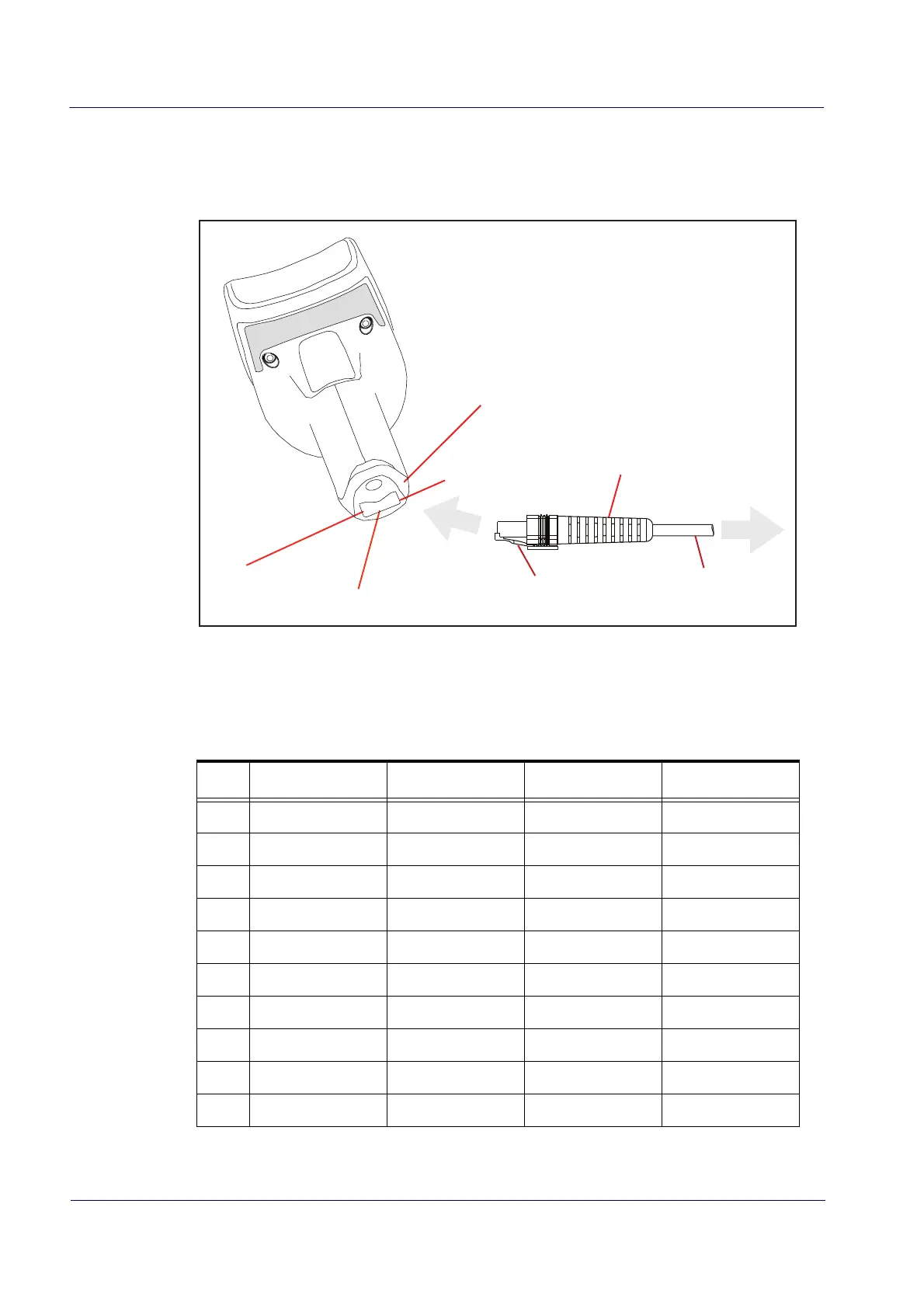
Figure 10 and Tab le 46 provide standard pinout information for the interface cable.
Figure 10. Standard Cable Pinouts: Handheld
Pin 10
Cable Clip (Latch)
To Host
Cable
Cable Strain Relief
Bottom of Scanner
Interface Cable Port
Pin 1
The signal descriptions in Ta bl e 46 apply to the connector on the reader and are for reference on-
ly.
Table 46.
Standard Cable Pinouts — Handheld (QD24XX model)
Pin RS-232 OEM USB Keyboard Wedge
1 RTS (out)
2 D+ CLKIN (KBD side)
3 D- DATAIN (KBD side)
4 GND GND GND GND
5 RX
6 TX
7 VCC VCC VCC VCC
8 IBM_B CLKOUT (PC side)
9 IBM_A DATAOUT (PC side)
10 CTS (in)
 Loading...