ES601Plus OPERATING MANUAL
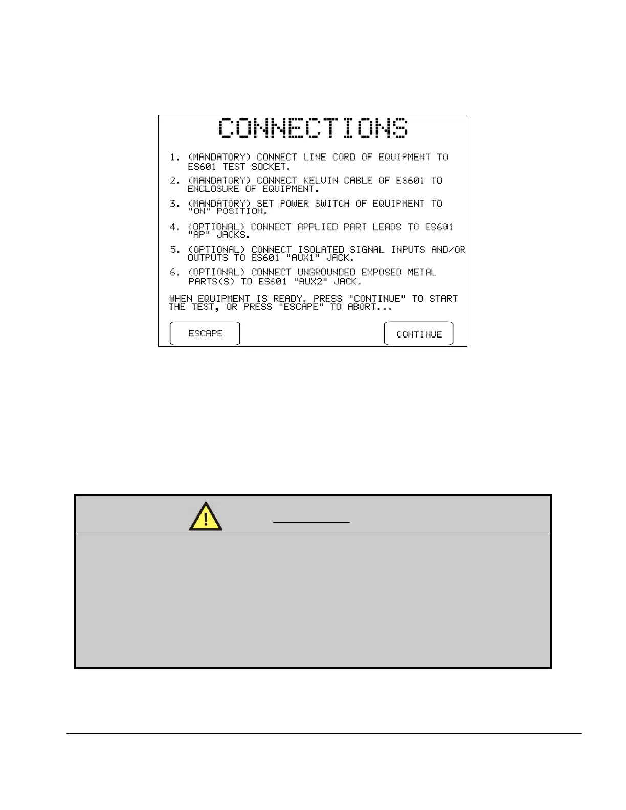
Fig u re 32 - DUT connection instructions for IEC60601 test.
According to the CONNECTIONS menu, at minimum an IEC60601 test will require the user to
connect the DUT to the test socket and the Kelvin Cable of ES601Plus to the enclosure of the
DUT. The power switch of the DUT must also be set to "ON" before the test is started. Depending
on how the user has chosen to set up the test via preceding menus, additional connections may be
required between AP jacks on ES601Plus and DUT applied parts; between AUX1 of ES601Plus
and DUT signal I/O; and between AUX2 and exposed ungrounded metal on the DUT.
WARNING:
If testing of Ty p e BF or Ty p e CF applied parts has been enabled, HIGH VOLTAGE (MAP
voltage) will be periodically output from the AP jacks during the test.
The MAP voltage is isolated from the AC mains and is internally current-limited to 8 milliamperes
maximum at 264 VAC output. Unterminated leads attached to the AP jacks therefore present a
minor, non-lethal shock hazard to the careless user.
Always take care to make proper electrical connections to the DUT before starting a leakage test.
Disconnect all unused leads or cables from the AP jacks on ES601Plus.
Manual Testing/Chapter 5 # Page 73
 Loading...