2.4.2 Specific state sequences supported by the DW1000
The DW1000 supports a number of state sequences intended to minimize power consumption in certain
applications. These are: -
In SNIFF mode the DW1000 alternates between the RX (on) and the IDLE (off) states.
Further details on this mode are given in section 4.5.1 – SNIFF.
LOW DUTY
CYCLE SNIFF
MODE
In Low duty-cycle SNIFF mode, where the off time is larger, the DW1000 can be
configured to spend this off time in the INIT state which is lower power than the IDLE
state (used for the off period of a SNIFF). Further details of this mode are given in
section 4.5.2 – Low duty-cycle SNIFF.
Low-Power Listening mode is a special mode where the receiver spends most its time in
a low power (SLEEP or DEEPSLEEP) state only waking up occasionally to sample the air
for a message. This feature is described in detail in section 4.4 – Low-Power Listening
2.5 Default Configuration on Power Up
DW1000 is a highly configurable transceiver with many features. The register reset values have been
selected with the intention of minimising user configuration required. The default configuration may be
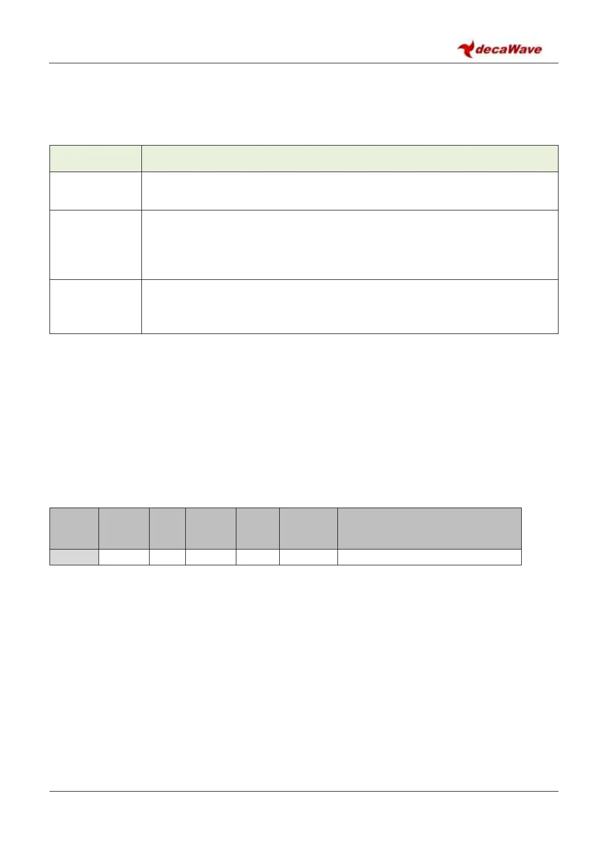
summarised as being channel 5, preamble code 4 and mode 2. Channel numbers and preamble codes are as
specified in the standard, IEEE 802.15.4-2011 [1] and mode 2 is as specified in the DW1000 data sheet
modes and comprises the following configurations:
Table 2: Mode 2 Excerpt from DW1000 Data Sheet Operational Modes Table
Typical Use Case
(Refer to DW1000 user manual for further information)
RTLS, TDOA Scheme, Short Range, High Density
Some further details are given below on the specifics of the default device configuration. For full details the
reader may refer to the register map where the default value of each register is given, section 7 – The
DW1000 register set.
2.5.1 Default System Configuration
Much of the system configuration is configured in the SYS_CFG register, please see section Register file: 0x04
– System Configuration for a full description of the register contents and defaults.
By default, interrupt polarity is active high and all interrupts are disabled, see the SYS_CFG register for
interrupt polarity and the SYS_MASK and SYS_STATUS registers for interrupt configuration and information,
see sections Register file: 0x0E – System Event Mask Register and Register file: 0x0F – System Event Status
Register.