3 Message Transmission
3.1 Basic Transmission
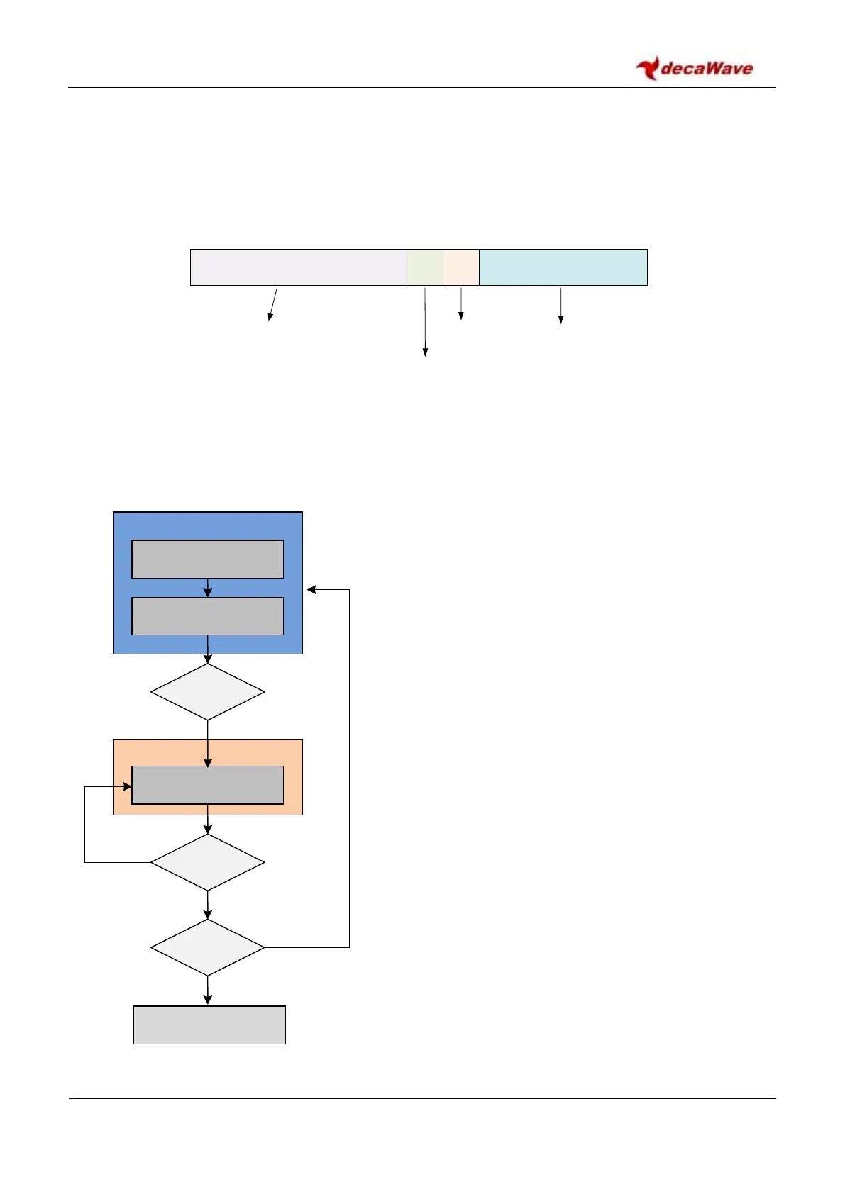
The transmission of data frames is one of the basic functions of the DW1000 transceiver. Figure 10 shows
the elements of the transmitted frame.
*Additional configurations marked “Extra” or “Extended” are proprietary to Decawave; see section 3.4 for details of
Extended Length Data Frames
Figure 10: Transmit Frame format
The modulation details of these frame elements can be found
in section 10 – APPENDIX 1: The IEEE 802.15.4 UWB physical
layer.
The transmit sequence is as shown in Figure 11. The DW1000
begins in the IDLE state awaiting instruction from the host
controller.
In order to transmit, the host controller must write data for
transmission to Register file: 0x09 – Transmit Data Buffer. The
desired selections for preamble length, data rate and PRF must
also be written to Register file: 0x08 – Transmit Frame Control.
Transmitter configuration is carried out in the IDLE state, but
frame configurations may be carried out during active transmit
as described in section 3.5 – High Speed Transmission.
Assuming all other relevant configurations have already been
made, the host controller initiates the transmission by setting
the TXSTRT control bit in Register file: 0x0D – System Control
Register. After transmission has been requested, the DW1000
automatically sends the complete frame; preamble, SFD, PHR
and data. The FCS (CRC) is automatically appended to the
message as an aid to the MAC layer framing.
The end of frame transmission is signalled to the host via the
TXFRS event status bit in Register file: 0x0F – System Event
Status Register, and the DW1000 returns to IDLE mode to await
new instructions.
Write Tx data to data buffer
Figure 11: Basic Transmit Sequence