7.2 Detailed register description
7.2.1 Terminology
Section 7.1 gives an overview of the DW1000 register set presenting all top level register file ID addresses in
Table 15. This section describes in detail the contents and functionality of these register files in separate sub
sections. In each case the row from Table 15 is reproduced with hex register file ID, its length, type,
mnemonic and one line description as follows:
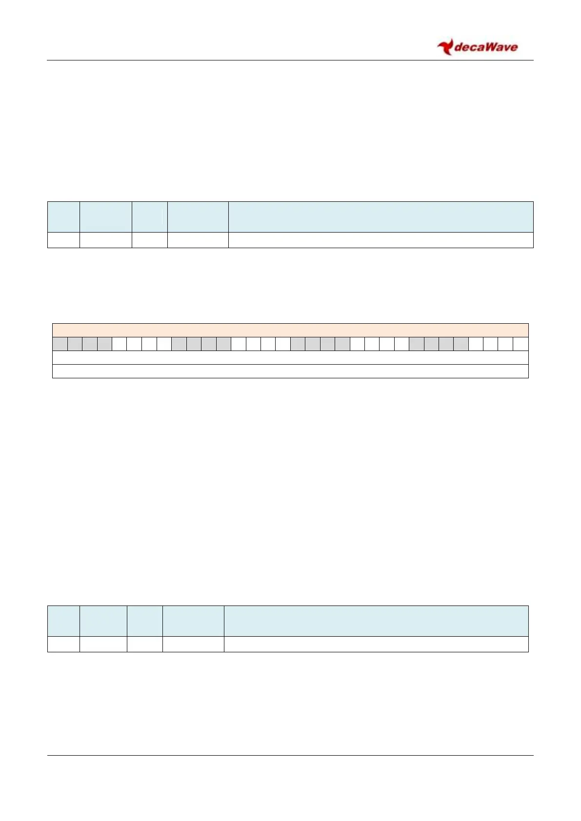
This is followed by a description of the parameters within that register file. All parameters are presented
with format REG:RR:SS, where RR is register file ID and SS is the sub address. Where a register is made up of
individual bits or bit-fields these are identified with mnemonic and default values as follows:
REG:RR:SS – Mnemonic – one line description
<bits or bit-fields identified by a quoted mnemonic>
<default power-on-reset values are quoted as bits or values>
Then the fields or bits identified are described individually in detail.
Because many parameters are 4-octets long, the default presentation of the register values is as a 32-bit
value. This may be sub-divided into fields of various bit widths down to single bit values. It should be noted
that when reading these values via the SPI interface the octets are output least significant octet first. Also of
note is the fact that the indexed addressing modes allow individual octets to be accessed – a technique that
may be employed to reduce SPI traffic when only part of a register needs to be read or written.
Note: unused or reserved registers return 0xDEADDEAD when read. Unused or reserved bits/ bit fields
within registers return the appropriate bits / bit fields from 0xDEADDEAD.
Each register file is described below:
7.2.2 Register file: 0x00 – Device Identifier
Device Identifier – includes device type and revision information
Register map register file 0x00 is the device identifier. This is hard-coded into the silicon. The value in this
register is read-only and cannot be overwritten by the host system. The device ID will be changed for any
silicon updates. The device ID register is ideal to use in the host µP to validate that the SPI interface is
operational. It is expected that the host system will validate that the device ID is the expected value,
supported by its software, before proceeding to use the IC.